* [RFC] Representing hardware connections via MC
@ 2016-02-26 12:13 Mauro Carvalho Chehab
  2016-02-26 13:13 ` Javier Martinez Canillas
                   ` (3 more replies)
  0 siblings, 4 replies; 33+ messages in thread
From: Mauro Carvalho Chehab @ 2016-02-26 12:13 UTC (permalink / raw)
  To: LMML; +Cc: Hans Verkuil, Sakari Ailus, Javier Martinez Canillas,
	Laurent Pinchart

We had some discussions on Feb, 12 about how to represent connectors via
the Media Controller:
	https://linuxtv.org/irc/irclogger_log/v4l?date=2016-02-12,Fri&sel=31#l27

We tried to finish those discussions on the last two weeks, but people
doesn't seem to be available at the same time for the discussions. So,
let's proceed with the discussions via e-mail.

So, I'd like to do such discussions via e-mail, as we need to close
this question next week.

QUESTION:
========

How to represent the hardware connection for inputs (and outputs) like:
	- Composite TV video;
	- stereo analog audio;
	- S-Video;
	- HDMI

Problem description:
===================

During the MC summit last year, we decided to add an entity called
"connector" for such things. So, we added, so far, 3 types of
connectors:

#define MEDIA_ENT_F_CONN_RF		(MEDIA_ENT_F_BASE + 10001)
#define MEDIA_ENT_F_CONN_SVIDEO		(MEDIA_ENT_F_BASE + 10002)
#define MEDIA_ENT_F_CONN_COMPOSITE	(MEDIA_ENT_F_BASE + 10003)

However, while implementing it, we saw that the mapping on hardware
is actually more complex, as one physical connector may have multiple
signals with can eventually used on a different way.

One simple example of this is the S-Video connector. It has internally
two video streams, one for chrominance and another one for luminance.

It is very common for vendors to ship devices with a S-Video input
and a "S-Video to RCA" cable.

At the driver's level, drivers need to know if such cable is
plugged, as they need to configure a different input setting to
enable either S-Video or composite decoding.

So, the V4L2 API usually maps "S-Video" on a different input
than "Composite over S-Video". This can be seen, for example, at the
saa7134 driver, who gained recently support for MC.

Additionally, it is interesting to describe the physical aspects
of the connector (color, position, label, etc).

Proposal:
========

It seems that there was an agreement that the physical aspects of
the connector should be mapped via the upcoming properties API,
with the properties present only when it is possible to find them
in the hardware. So, it seems that all such properties should be
optional.

However, we didn't finish the meeting, as we ran out of time. Yet,
I guess the last proposal there fulfills the requirements. So,
let's focus our discussions on it. So, let me formulate it as a
proposal

We should represent the entities based on the inputs. So, for the
already implemented entities, we'll have, instead:

#define MEDIA_ENT_F_INPUT_RF		(MEDIA_ENT_F_BASE + 10001)
#define MEDIA_ENT_F_INPUT_SVIDEO	(MEDIA_ENT_F_BASE + 10002)
#define MEDIA_ENT_F_INPUT_COMPOSITE	(MEDIA_ENT_F_BASE + 10003)

The MEDIA_ENT_F_INPUT_RF and MEDIA_ENT_F_INPUT_COMPOSITE will have
just one sink PAD each, as they carry just one signal. As we're
describing the logical input, it doesn't matter the physical
connector type. So, except for re-naming the define, nothing
changes for them.

Devices with S-Video input will have one MEDIA_ENT_F_INPUT_SVIDEO
per each different S-Video input. Each one will have two sink pads,
one for the Y signal and another for the C signal.

So, a device like Terratec AV350, that has one Composite and one
S-Video input[1] would be represented as:
	https://mchehab.fedorapeople.org/terratec_av350-modified.png


[1] Physically, it has a SCART connector that could be enabled
via a physical switch, but logically, the device will still switch
from S-Video over SCART or composite over SCART.

More complex devices would be represented like:
	https://hverkuil.home.xs4all.nl/adv7604.png
	https://hverkuil.home.xs4all.nl/adv7842.png

NOTE:

The labels at the PADs currently can't be represented, but the
idea is adding it as a property via the upcoming properties API.

Anyone disagree?

Regards,
Mauro

^ permalink raw reply	[flat|nested] 33+ messages in thread
* Re: [RFC] Representing hardware connections via MC 2016-02-26 12:13 [RFC] Representing hardware connections via MC Mauro Carvalho Chehab @ 2016-02-26 13:13 ` Javier Martinez Canillas 2016-02-26 13:48 ` Mauro Carvalho Chehab 2016-03-02 11:10 ` Laurent Pinchart 2016-02-26 13:23 ` Hans Verkuil ` (2 subsequent siblings) 3 siblings, 2 replies; 33+ messages in thread From: Javier Martinez Canillas @ 2016-02-26 13:13 UTC (permalink / raw) To: Mauro Carvalho Chehab, LMML; +Cc: Hans Verkuil, Sakari Ailus, Laurent Pinchart Hello Mauro, On 02/26/2016 09:13 AM, Mauro Carvalho Chehab wrote: > We had some discussions on Feb, 12 about how to represent connectors via > the Media Controller: > https://linuxtv.org/irc/irclogger_log/v4l?date=2016-02-12,Fri&sel=31#l27 > > We tried to finish those discussions on the last two weeks, but people > doesn't seem to be available at the same time for the discussions. So, > let's proceed with the discussions via e-mail. > > So, I'd like to do such discussions via e-mail, as we need to close > this question next week. > > QUESTION: > ======== > > How to represent the hardware connection for inputs (and outputs) like: > - Composite TV video; > - stereo analog audio; > - S-Video; > - HDMI > > Problem description: > =================== > > During the MC summit last year, we decided to add an entity called > "connector" for such things. So, we added, so far, 3 types of > connectors: > > #define MEDIA_ENT_F_CONN_RF (MEDIA_ENT_F_BASE + 10001) > #define MEDIA_ENT_F_CONN_SVIDEO (MEDIA_ENT_F_BASE + 10002) > #define MEDIA_ENT_F_CONN_COMPOSITE (MEDIA_ENT_F_BASE + 10003) > > However, while implementing it, we saw that the mapping on hardware > is actually more complex, as one physical connector may have multiple > signals with can eventually used on a different way. > > One simple example of this is the S-Video connector. It has internally > two video streams, one for chrominance and another one for luminance. > > It is very common for vendors to ship devices with a S-Video input > and a "S-Video to RCA" cable. > > At the driver's level, drivers need to know if such cable is > plugged, as they need to configure a different input setting to > enable either S-Video or composite decoding. > > So, the V4L2 API usually maps "S-Video" on a different input > than "Composite over S-Video". This can be seen, for example, at the > saa7134 driver, who gained recently support for MC. > > Additionally, it is interesting to describe the physical aspects > of the connector (color, position, label, etc). > > Proposal: > ======== > > It seems that there was an agreement that the physical aspects of > the connector should be mapped via the upcoming properties API, > with the properties present only when it is possible to find them > in the hardware. So, it seems that all such properties should be > optional. > > However, we didn't finish the meeting, as we ran out of time. Yet, > I guess the last proposal there fulfills the requirements. So, > let's focus our discussions on it. So, let me formulate it as a > proposal > Thanks for writing down as a proposal what was discussed over IRC. > We should represent the entities based on the inputs. So, for the > already implemented entities, we'll have, instead: > > #define MEDIA_ENT_F_INPUT_RF (MEDIA_ENT_F_BASE + 10001) > #define MEDIA_ENT_F_INPUT_SVIDEO (MEDIA_ENT_F_BASE + 10002) > #define MEDIA_ENT_F_INPUT_COMPOSITE (MEDIA_ENT_F_BASE + 10003) > > The MEDIA_ENT_F_INPUT_RF and MEDIA_ENT_F_INPUT_COMPOSITE will have > just one sink PAD each, as they carry just one signal. As we're > describing the logical input, it doesn't matter the physical > connector type. So, except for re-naming the define, nothing > changes for them. > > Devices with S-Video input will have one MEDIA_ENT_F_INPUT_SVIDEO > per each different S-Video input. Each one will have two sink pads, > one for the Y signal and another for the C signal. > > So, a device like Terratec AV350, that has one Composite and one > S-Video input[1] would be represented as: > https://mchehab.fedorapeople.org/terratec_av350-modified.png > > > [1] Physically, it has a SCART connector that could be enabled > via a physical switch, but logically, the device will still switch > from S-Video over SCART or composite over SCART. > > More complex devices would be represented like: > https://hverkuil.home.xs4all.nl/adv7604.png > https://hverkuil.home.xs4all.nl/adv7842.png > > NOTE: > > The labels at the PADs currently can't be represented, but the > idea is adding it as a property via the upcoming properties API. > > Anyone disagree? > What you described is what I understood that was the last proposal and I believe everyone agreed that it was the way to move forward. I've just one question, why the PAD's labels / symbolic names will be added as a property instead of just having a name or label field in struct media_pad? For example, in the Terratec AV350 chip you mentioned, the AIP1{A,B} source pads are real pins in the tvp5150 package and are documented in the datasheet and a S-Video connector will always have a Y and C sinks pads for the 2 signals and a Composite connector a single pad. So why can't the driver just set those when creating the connectors entities? Or maybe I'm misunderstanding how the properties API work. > Regards, > Mauro > Best regards, -- Javier Martinez Canillas Open Source Group Samsung Research America ^ permalink raw reply [flat|nested] 33+ messages in thread
* Re: [RFC] Representing hardware connections via MC
  2016-02-26 13:13 ` Javier Martinez Canillas
@ 2016-02-26 13:48   ` Mauro Carvalho Chehab
  2016-03-02 11:10   ` Laurent Pinchart
  1 sibling, 0 replies; 33+ messages in thread
From: Mauro Carvalho Chehab @ 2016-02-26 13:48 UTC (permalink / raw)
  To: Javier Martinez Canillas
  Cc: LMML, Hans Verkuil, Sakari Ailus, Laurent Pinchart

Em Fri, 26 Feb 2016 10:13:48 -0300
Javier Martinez Canillas <javier@osg.samsung.com> escreveu:

> Hello Mauro,
>
> On 02/26/2016 09:13 AM, Mauro Carvalho Chehab wrote:
> > We had some discussions on Feb, 12 about how to represent connectors via
> > the Media Controller:
> > 	https://linuxtv.org/irc/irclogger_log/v4l?date=2016-02-12,Fri&sel=31#l27
> >
> > We tried to finish those discussions on the last two weeks, but people
> > doesn't seem to be available at the same time for the discussions. So,
> > let's proceed with the discussions via e-mail.
> >
> > So, I'd like to do such discussions via e-mail, as we need to close
> > this question next week.
> >
> > QUESTION:
> > ========
> >
> > How to represent the hardware connection for inputs (and outputs) like:
> > 	- Composite TV video;
> > 	- stereo analog audio;
> > 	- S-Video;
> > 	- HDMI
> >
> > Problem description:
> > ===================
> >
> > During the MC summit last year, we decided to add an entity called
> > "connector" for such things. So, we added, so far, 3 types of
> > connectors:
> >
> > #define MEDIA_ENT_F_CONN_RF		(MEDIA_ENT_F_BASE + 10001)
> > #define MEDIA_ENT_F_CONN_SVIDEO		(MEDIA_ENT_F_BASE + 10002)
> > #define MEDIA_ENT_F_CONN_COMPOSITE	(MEDIA_ENT_F_BASE + 10003)
> >
> > However, while implementing it, we saw that the mapping on hardware
> > is actually more complex, as one physical connector may have multiple
> > signals with can eventually used on a different way.
> >
> > One simple example of this is the S-Video connector. It has internally
> > two video streams, one for chrominance and another one for luminance.
> >
> > It is very common for vendors to ship devices with a S-Video input
> > and a "S-Video to RCA" cable.
> >
> > At the driver's level, drivers need to know if such cable is
> > plugged, as they need to configure a different input setting to
> > enable either S-Video or composite decoding.
> >
> > So, the V4L2 API usually maps "S-Video" on a different input
> > than "Composite over S-Video". This can be seen, for example, at the
> > saa7134 driver, who gained recently support for MC.
> >
> > Additionally, it is interesting to describe the physical aspects
> > of the connector (color, position, label, etc).
> >
> > Proposal:
> > ========
> >
> > It seems that there was an agreement that the physical aspects of
> > the connector should be mapped via the upcoming properties API,
> > with the properties present only when it is possible to find them
> > in the hardware. So, it seems that all such properties should be
> > optional.
> >
> > However, we didn't finish the meeting, as we ran out of time. Yet,
> > I guess the last proposal there fulfills the requirements. So,
> > let's focus our discussions on it. So, let me formulate it as a
> > proposal
> >
>
> Thanks for writing down as a proposal what was discussed over IRC.
>
> > We should represent the entities based on the inputs. So, for the
> > already implemented entities, we'll have, instead:
> >
> > #define MEDIA_ENT_F_INPUT_RF		(MEDIA_ENT_F_BASE + 10001)
> > #define MEDIA_ENT_F_INPUT_SVIDEO	(MEDIA_ENT_F_BASE + 10002)
> > #define MEDIA_ENT_F_INPUT_COMPOSITE	(MEDIA_ENT_F_BASE + 10003)
> >
> > The MEDIA_ENT_F_INPUT_RF and MEDIA_ENT_F_INPUT_COMPOSITE will have
> > just one sink PAD each, as they carry just one signal. As we're
> > describing the logical input, it doesn't matter the physical
> > connector type. So, except for re-naming the define, nothing
> > changes for them.
> >
> > Devices with S-Video input will have one MEDIA_ENT_F_INPUT_SVIDEO
> > per each different S-Video input. Each one will have two sink pads,
> > one for the Y signal and another for the C signal.
> >
> > So, a device like Terratec AV350, that has one Composite and one
> > S-Video input[1] would be represented as:
> > 	https://mchehab.fedorapeople.org/terratec_av350-modified.png
> >
> >
> > [1] Physically, it has a SCART connector that could be enabled
> > via a physical switch, but logically, the device will still switch
> > from S-Video over SCART or composite over SCART.
> >
> > More complex devices would be represented like:
> > 	https://hverkuil.home.xs4all.nl/adv7604.png
> > 	https://hverkuil.home.xs4all.nl/adv7842.png
> >
> > NOTE:
> >
> > The labels at the PADs currently can't be represented, but the
> > idea is adding it as a property via the upcoming properties API.
> >
> > Anyone disagree?
> >
>
> What you described is what I understood that was the last proposal
> and I believe everyone agreed that it was the way to move forward.
>
> I've just one question, why the PAD's labels / symbolic names will
> be added as a property instead of just having a name or label field
> in struct media_pad?
>
> For example, in the Terratec AV350 chip you mentioned, the AIP1{A,B}
> source pads are real pins in the tvp5150 package and are documented
> in the datasheet and a S-Video connector will always have a Y and C
> sinks pads for the 2 signals and a Composite connector a single pad.
>
> So why can't the driver just set those when creating the connectors
> entities? Or maybe I'm misunderstanding how the properties API work.

Well, we could add a "label" to pads, but not all pads need it.
Adding optional fields to the structs will increase their size
for all PADs, even for the ones that won't need it. That's
even worse for labels, as we would spend something like 32 or
64 bytes for it.

The idea behind the properties API is to allow adding extra
fields to graph objects. Once we add it, the driver could fill the
labels where this is needed, without spending memory for the
graph objects that won't need.

OK, we need to see the actual patches for it. Sakari has been
working on it, but I've no idea if he has some patches to
submit for us to review, even as RFC, but he did a proposal
for it last year:
	https://www.spinics.net/lists/linux-media/msg90160.html

In this sense, on a device like:
	http://terratec.ultron.info/Video/Grabster/GrabsterAV250MX/Images/Grabster_AV_250_MX_L.jpg

We would represent the properties via the properties API with:

"entity": {
	"id": 1,
	"label": "S-Video",
	"color": "black",
	"connector": "4-pin mini-DIN"
}

"entity": {
	"id": 2,
	"label": "Composite",
	"color": "yellow",
	"connector": "RCA"
}

"pad": {
	"id": 3,
	"label": "A1P1A",
}

"pad": {
	"id": 4,
	"label": "A1P1B",
}

Representing the audio input (we would need a new entity function
for it) would be something like:

"entity": {
	"id": 5,
	"label": "Audio"
	"channels": 2
}

"pad": {
	"id": 6,
	"label": "L",
	"color" : "white",
	"connector": "RCA"
}

"pad": {
	"id": 7,
	"label": "R"
	"color" : "red",
	"connector": "RCA"
}


Please notice that we don't need to agree yet about the properties
API definitions, as this is a separate discussion that may be
required after we start discussing the properties API patchset,
after its submission.

--
Thanks,
Mauro

^ permalink raw reply	[flat|nested] 33+ messages in thread
* Re: [RFC] Representing hardware connections via MC
  2016-02-26 13:13 ` Javier Martinez Canillas
  2016-02-26 13:48   ` Mauro Carvalho Chehab
@ 2016-03-02 11:10   ` Laurent Pinchart
  1 sibling, 0 replies; 33+ messages in thread
From: Laurent Pinchart @ 2016-03-02 11:10 UTC (permalink / raw)
  To: Javier Martinez Canillas
  Cc: Mauro Carvalho Chehab, LMML, Hans Verkuil, Sakari Ailus

Hi Javier,

On Friday 26 February 2016 10:13:48 Javier Martinez Canillas wrote:
> On 02/26/2016 09:13 AM, Mauro Carvalho Chehab wrote:
> > We had some discussions on Feb, 12 about how to represent connectors via
> >
> > the Media Controller:
> > 	https://linuxtv.org/irc/irclogger_log/v4l?date=2016-02-12,Fri&sel=31#l27
> >
> > We tried to finish those discussions on the last two weeks, but people
> > doesn't seem to be available at the same time for the discussions. So,
> > let's proceed with the discussions via e-mail.
> >
> > So, I'd like to do such discussions via e-mail, as we need to close
> > this question next week.
> >
> > QUESTION:
> > ========
> >
> > How to represent the hardware connection for inputs (and outputs) like:
> > 	- Composite TV video;
> > 	- stereo analog audio;
> > 	- S-Video;
> > 	- HDMI
> >
> > Problem description:
> > ===================
> >
> > During the MC summit last year, we decided to add an entity called
> > "connector" for such things. So, we added, so far, 3 types of
> > connectors:
> >
> > #define MEDIA_ENT_F_CONN_RF		(MEDIA_ENT_F_BASE + 10001)
> > #define MEDIA_ENT_F_CONN_SVIDEO		(MEDIA_ENT_F_BASE + 10002)
> > #define MEDIA_ENT_F_CONN_COMPOSITE	(MEDIA_ENT_F_BASE + 10003)
> >
> > However, while implementing it, we saw that the mapping on hardware
> > is actually more complex, as one physical connector may have multiple
> > signals with can eventually used on a different way.
> >
> > One simple example of this is the S-Video connector. It has internally
> > two video streams, one for chrominance and another one for luminance.
> >
> > It is very common for vendors to ship devices with a S-Video input
> > and a "S-Video to RCA" cable.
> >
> > At the driver's level, drivers need to know if such cable is
> > plugged, as they need to configure a different input setting to
> > enable either S-Video or composite decoding.
> >
> > So, the V4L2 API usually maps "S-Video" on a different input
> > than "Composite over S-Video". This can be seen, for example, at the
> > saa7134 driver, who gained recently support for MC.
> >
> > Additionally, it is interesting to describe the physical aspects
> > of the connector (color, position, label, etc).
> >
> > Proposal:
> > ========
> >
> > It seems that there was an agreement that the physical aspects of
> > the connector should be mapped via the upcoming properties API,
> > with the properties present only when it is possible to find them
> > in the hardware. So, it seems that all such properties should be
> > optional.
> >
> > However, we didn't finish the meeting, as we ran out of time. Yet,
> > I guess the last proposal there fulfills the requirements. So,
> > let's focus our discussions on it. So, let me formulate it as a
> > proposal
>
> Thanks for writing down as a proposal what was discussed over IRC.
>
> > We should represent the entities based on the inputs. So, for the
> > already implemented entities, we'll have, instead:
> >
> > #define MEDIA_ENT_F_INPUT_RF		(MEDIA_ENT_F_BASE + 10001)
> > #define MEDIA_ENT_F_INPUT_SVIDEO	(MEDIA_ENT_F_BASE + 10002)
> > #define MEDIA_ENT_F_INPUT_COMPOSITE	(MEDIA_ENT_F_BASE + 10003)
> >
> > The MEDIA_ENT_F_INPUT_RF and MEDIA_ENT_F_INPUT_COMPOSITE will have
> > just one sink PAD each, as they carry just one signal. As we're
> > describing the logical input, it doesn't matter the physical
> > connector type. So, except for re-naming the define, nothing
> > changes for them.
> >
> > Devices with S-Video input will have one MEDIA_ENT_F_INPUT_SVIDEO
> > per each different S-Video input. Each one will have two sink pads,
> > one for the Y signal and another for the C signal.
> >
> > So, a device like Terratec AV350, that has one Composite and one
> >
> > S-Video input[1] would be represented as:
> > 	https://mchehab.fedorapeople.org/terratec_av350-modified.png
> >
> > [1] Physically, it has a SCART connector that could be enabled
> > via a physical switch, but logically, the device will still switch
> > from S-Video over SCART or composite over SCART.
> >
> > More complex devices would be represented like:
> > 	https://hverkuil.home.xs4all.nl/adv7604.png
> > 	https://hverkuil.home.xs4all.nl/adv7842.png
> >
> > NOTE:
> >
> > The labels at the PADs currently can't be represented, but the
> > idea is adding it as a property via the upcoming properties API.
> >
> > Anyone disagree?
>
> What you described is what I understood that was the last proposal
> and I believe everyone agreed that it was the way to move forward.

Creating input entities instead of connector entities was indeed proposed, but
when we closed the meeting I was still pondering on the implications, I
wouldn't call that an agreement on the way to move forward :-)

> I've just one question, why the PAD's labels / symbolic names will
> be added as a property instead of just having a name or label field
> in struct media_pad?

Same reason as for entity labels in general, using the property API will avoid
wasting space for an optional string property that would otherwise have to be
stored in every pad structure (and we'll have lots of them). Another
additional benefit of the property API (or at least of the way I envision it)
is that we won't be bound by a predefined short(ish) label maximum length.

> For example, in the Terratec AV350 chip you mentioned, the AIP1{A,B}
> source pads are real pins in the tvp5150 package and are documented
> in the datasheet and a S-Video connector will always have a Y and C
> sinks pads for the 2 signals and a Composite connector a single pad.
>
> So why can't the driver just set those when creating the connectors
> entities? Or maybe I'm misunderstanding how the properties API work.

Another point that needs to be discussed, when we'll talk about pad labels, is
how to differentiate pads from userspace in general. Applications will need to
refer to pads when using kernel APIs (to set formats for instance), so they
will need a way to find the pad(s) they're interested in. Given that pad IDs
are not stable we can't rely on them to look a pad up. So far we've always
used pad indexes for this purpose, and I would prefer keeping that as the
prime pad lookup method instead of making it string-based. This doesn't
preclude adding labels for informative purpose of course.

I wonder if we can keep this topic separate from the connector entities
discussion, or if it needs to be discussed already. For instance if we decide
to model entities in such a way that the number of pads can vary depending on
the way the entity is instantiated, we'll have to make sure already that we
can offer userspace a way to locate pads. This doesn't have to involve labels,
but pad look up must be considered.

--
Regards,

Laurent Pinchart


^ permalink raw reply	[flat|nested] 33+ messages in thread
* Re: [RFC] Representing hardware connections via MC
  2016-02-26 12:13 [RFC] Representing hardware connections via MC Mauro Carvalho Chehab
  2016-02-26 13:13 ` Javier Martinez Canillas
@ 2016-02-26 13:23 ` Hans Verkuil
  2016-02-26 13:47   ` Javier Martinez Canillas
  2016-02-26 14:00   ` Mauro Carvalho Chehab
  2016-03-02 10:34 ` Laurent Pinchart
  2016-03-02 14:16 ` Sakari Ailus
  3 siblings, 2 replies; 33+ messages in thread
From: Hans Verkuil @ 2016-02-26 13:23 UTC (permalink / raw)
  To: Mauro Carvalho Chehab, LMML
  Cc: Sakari Ailus, Javier Martinez Canillas, Laurent Pinchart

On 02/26/2016 01:13 PM, Mauro Carvalho Chehab wrote:
> We had some discussions on Feb, 12 about how to represent connectors via
> the Media Controller:
> 	https://linuxtv.org/irc/irclogger_log/v4l?date=2016-02-12,Fri&sel=31#l27
>
> We tried to finish those discussions on the last two weeks, but people
> doesn't seem to be available at the same time for the discussions. So,
> let's proceed with the discussions via e-mail.
>
> So, I'd like to do such discussions via e-mail, as we need to close
> this question next week.
>
> QUESTION:
> ========
>
> How to represent the hardware connection for inputs (and outputs) like:
> 	- Composite TV video;
> 	- stereo analog audio;
> 	- S-Video;
> 	- HDMI
>
> Problem description:
> ===================
>
> During the MC summit last year, we decided to add an entity called
> "connector" for such things. So, we added, so far, 3 types of
> connectors:
>
> #define MEDIA_ENT_F_CONN_RF		(MEDIA_ENT_F_BASE + 10001)
> #define MEDIA_ENT_F_CONN_SVIDEO		(MEDIA_ENT_F_BASE + 10002)
> #define MEDIA_ENT_F_CONN_COMPOSITE	(MEDIA_ENT_F_BASE + 10003)
>
> However, while implementing it, we saw that the mapping on hardware
> is actually more complex, as one physical connector may have multiple
> signals with can eventually used on a different way.
>
> One simple example of this is the S-Video connector. It has internally
> two video streams, one for chrominance and another one for luminance.
>
> It is very common for vendors to ship devices with a S-Video input
> and a "S-Video to RCA" cable.
>
> At the driver's level, drivers need to know if such cable is
> plugged, as they need to configure a different input setting to
> enable either S-Video or composite decoding.
>
> So, the V4L2 API usually maps "S-Video" on a different input
> than "Composite over S-Video". This can be seen, for example, at the
> saa7134 driver, who gained recently support for MC.
>
> Additionally, it is interesting to describe the physical aspects
> of the connector (color, position, label, etc).
>
> Proposal:
> ========
>
> It seems that there was an agreement that the physical aspects of
> the connector should be mapped via the upcoming properties API,
> with the properties present only when it is possible to find them
> in the hardware. So, it seems that all such properties should be
> optional.
>
> However, we didn't finish the meeting, as we ran out of time. Yet,
> I guess the last proposal there fulfills the requirements. So,
> let's focus our discussions on it. So, let me formulate it as a
> proposal
>
> We should represent the entities based on the inputs. So, for the
> already implemented entities, we'll have, instead:
>
> #define MEDIA_ENT_F_INPUT_RF		(MEDIA_ENT_F_BASE + 10001)
> #define MEDIA_ENT_F_INPUT_SVIDEO	(MEDIA_ENT_F_BASE + 10002)
> #define MEDIA_ENT_F_INPUT_COMPOSITE	(MEDIA_ENT_F_BASE + 10003)
>
> The MEDIA_ENT_F_INPUT_RF and MEDIA_ENT_F_INPUT_COMPOSITE will have
> just one sink PAD each, as they carry just one signal. As we're
> describing the logical input, it doesn't matter the physical
> connector type. So, except for re-naming the define, nothing
> changes for them.

What if my device has an SVIDEO output (e.g. ivtv)? 'INPUT' denotes
the direction, and I don't think that's something you want in the
define for the connector entity.

As was discussed on irc we are really talking about signals received
or transmitted by/from a connector. I still prefer F_SIG_ or F_SIGNAL_
or F_CONN_SIG_ or something along those lines.

I'm not sure where F_INPUT came from, certainly not from the irc
discussion.

> Devices with S-Video input will have one MEDIA_ENT_F_INPUT_SVIDEO
> per each different S-Video input. Each one will have two sink pads,
> one for the Y signal and another for the C signal.
>
> So, a device like Terratec AV350, that has one Composite and one
> S-Video input[1] would be represented as:
> 	https://mchehab.fedorapeople.org/terratec_av350-modified.png
>
>
> [1] Physically, it has a SCART connector that could be enabled
> via a physical switch, but logically, the device will still switch
> from S-Video over SCART or composite over SCART.
>
> More complex devices would be represented like:
> 	https://hverkuil.home.xs4all.nl/adv7604.png
> 	https://hverkuil.home.xs4all.nl/adv7842.png
>
> NOTE:
>
> The labels at the PADs currently can't be represented, but the
> idea is adding it as a property via the upcoming properties API.

I think this is a separate discussion. It's not needed for now.
When working on the adv7604/7842 examples I realized that pad names help
understand the topology a lot better, but they are not needed for the actual
functionality.

>
> Anyone disagree?

I agree except for the naming.

Regards,

	Hans

^ permalink raw reply	[flat|nested] 33+ messages in thread
* Re: [RFC] Representing hardware connections via MC
  2016-02-26 13:23 ` Hans Verkuil
@ 2016-02-26 13:47   ` Javier Martinez Canillas
  2016-02-26 14:05     ` Mauro Carvalho Chehab
  2016-02-26 14:00   ` Mauro Carvalho Chehab
  1 sibling, 1 reply; 33+ messages in thread
From: Javier Martinez Canillas @ 2016-02-26 13:47 UTC (permalink / raw)
  To: Hans Verkuil, Mauro Carvalho Chehab, LMML; +Cc: Sakari Ailus, Laurent Pinchart

Hello Hans,

On 02/26/2016 10:23 AM, Hans Verkuil wrote:
> On 02/26/2016 01:13 PM, Mauro Carvalho Chehab wrote:

[snip]

>>
>> #define MEDIA_ENT_F_INPUT_RF		(MEDIA_ENT_F_BASE + 10001)
>> #define MEDIA_ENT_F_INPUT_SVIDEO	(MEDIA_ENT_F_BASE + 10002)
>> #define MEDIA_ENT_F_INPUT_COMPOSITE	(MEDIA_ENT_F_BASE + 10003)
>>
>> The MEDIA_ENT_F_INPUT_RF and MEDIA_ENT_F_INPUT_COMPOSITE will have
>> just one sink PAD each, as they carry just one signal. As we're
>> describing the logical input, it doesn't matter the physical
>> connector type. So, except for re-naming the define, nothing
>> changes for them.
>
> What if my device has an SVIDEO output (e.g. ivtv)? 'INPUT' denotes
> the direction, and I don't think that's something you want in the
> define for the connector entity.
>
> As was discussed on irc we are really talking about signals received
> or transmitted by/from a connector. I still prefer F_SIG_ or F_SIGNAL_
> or F_CONN_SIG_ or something along those lines.
>
> I'm not sure where F_INPUT came from, certainly not from the irc
> discussion.
>

Indeed, I missed that when reviewing the proposal.

>> Devices with S-Video input will have one MEDIA_ENT_F_INPUT_SVIDEO
>> per each different S-Video input. Each one will have two sink pads,
>> one for the Y signal and another for the C signal.
>>
>> So, a device like Terratec AV350, that has one Composite and one
>> S-Video input[1] would be represented as:
>> 	https://mchehab.fedorapeople.org/terratec_av350-modified.png
>>
>>
>> [1] Physically, it has a SCART connector that could be enabled
>> via a physical switch, but logically, the device will still switch
>> from S-Video over SCART or composite over SCART.
>>
>> More complex devices would be represented like:
>> 	https://hverkuil.home.xs4all.nl/adv7604.png
>> 	https://hverkuil.home.xs4all.nl/adv7842.png
>>
>> NOTE:
>>
>> The labels at the PADs currently can't be represented, but the
>> idea is adding it as a property via the upcoming properties API.
>
> I think this is a separate discussion. It's not needed for now.
> When working on the adv7604/7842 examples I realized that pad names help
> understand the topology a lot better, but they are not needed for the actual
> functionality.
>

It's true that is a separate discussion but it would be good to agree
on it at least before the G_TOPOLOGY ioctl is available since we may
need to add a label/name field to struct media_v2_pad, that is filled
by the kernel and copied to user-space so it can't be changed later.

>>
>> Anyone disagree?
>
> I agree except for the naming.
>
> Regards,
>
> 	Hans
>

Best regards,
--
Javier Martinez Canillas
Open Source Group
Samsung Research America

^ permalink raw reply	[flat|nested] 33+ messages in thread
* Re: [RFC] Representing hardware connections via MC
  2016-02-26 13:47   ` Javier Martinez Canillas
@ 2016-02-26 14:05     ` Mauro Carvalho Chehab
  0 siblings, 0 replies; 33+ messages in thread
From: Mauro Carvalho Chehab @ 2016-02-26 14:05 UTC (permalink / raw)
  To: Javier Martinez Canillas
  Cc: Hans Verkuil, LMML, Sakari Ailus, Laurent Pinchart

Em Fri, 26 Feb 2016 10:47:56 -0300
Javier Martinez Canillas <javier@osg.samsung.com> escreveu:

> Hello Hans,
>
> On 02/26/2016 10:23 AM, Hans Verkuil wrote:
> > On 02/26/2016 01:13 PM, Mauro Carvalho Chehab wrote:
>
> [snip]
>
> >>
> >> #define MEDIA_ENT_F_INPUT_RF		(MEDIA_ENT_F_BASE + 10001)
> >> #define MEDIA_ENT_F_INPUT_SVIDEO	(MEDIA_ENT_F_BASE + 10002)
> >> #define MEDIA_ENT_F_INPUT_COMPOSITE	(MEDIA_ENT_F_BASE + 10003)
> >>
> >> The MEDIA_ENT_F_INPUT_RF and MEDIA_ENT_F_INPUT_COMPOSITE will have
> >> just one sink PAD each, as they carry just one signal. As we're
> >> describing the logical input, it doesn't matter the physical
> >> connector type. So, except for re-naming the define, nothing
> >> changes for them.
> >
> > What if my device has an SVIDEO output (e.g. ivtv)? 'INPUT' denotes
> > the direction, and I don't think that's something you want in the
> > define for the connector entity.
> >
> > As was discussed on irc we are really talking about signals received
> > or transmitted by/from a connector. I still prefer F_SIG_ or F_SIGNAL_
> > or F_CONN_SIG_ or something along those lines.
> >
> > I'm not sure where F_INPUT came from, certainly not from the irc
> > discussion.
> >
>
> Indeed, I missed that when reviewing the proposal.
>
> >> Devices with S-Video input will have one MEDIA_ENT_F_INPUT_SVIDEO
> >> per each different S-Video input. Each one will have two sink pads,
> >> one for the Y signal and another for the C signal.
> >>
> >> So, a device like Terratec AV350, that has one Composite and one
> >> S-Video input[1] would be represented as:
> >> 	https://mchehab.fedorapeople.org/terratec_av350-modified.png
> >>
> >>
> >> [1] Physically, it has a SCART connector that could be enabled
> >> via a physical switch, but logically, the device will still switch
> >> from S-Video over SCART or composite over SCART.
> >>
> >> More complex devices would be represented like:
> >> 	https://hverkuil.home.xs4all.nl/adv7604.png
> >> 	https://hverkuil.home.xs4all.nl/adv7842.png
> >>
> >> NOTE:
> >>
> >> The labels at the PADs currently can't be represented, but the
> >> idea is adding it as a property via the upcoming properties API.
> >
> > I think this is a separate discussion. It's not needed for now.
> > When working on the adv7604/7842 examples I realized that pad names help
> > understand the topology a lot better, but they are not needed for the actual
> > functionality.
> >
>
> It's true that is a separate discussion but it would be good to agree
> on it at least before the G_TOPOLOGY ioctl is available since we may
> need to add a label/name field to struct media_v2_pad, that is filled
> by the kernel and copied to user-space so it can't be changed later.

The idea when we did the MC workshop last year were to have the
structs with mandatory fields only, and to make it small, as we
wanted to get all topology with a single ioctl call.

pad labels is still a controversial concept, and it is optional,
as, for some entities (like DVB demuxes), it doesn't apply, as
a pad number is enough.

So, I don't think we should add it to the structure.

>
> >>
> >> Anyone disagree?
> >
> > I agree except for the naming.
> >
> > Regards,
> >
> > 	Hans
> >
>
> Best regards,


--
Thanks,
Mauro

^ permalink raw reply	[flat|nested] 33+ messages in thread
* Re: [RFC] Representing hardware connections via MC
  2016-02-26 13:23 ` Hans Verkuil
  2016-02-26 13:47   ` Javier Martinez Canillas
@ 2016-02-26 14:00   ` Mauro Carvalho Chehab
  2016-02-26 14:07     ` Hans Verkuil
  1 sibling, 1 reply; 33+ messages in thread
From: Mauro Carvalho Chehab @ 2016-02-26 14:00 UTC (permalink / raw)
  To: Hans Verkuil
  Cc: LMML, Sakari Ailus, Javier Martinez Canillas, Laurent Pinchart

Em Fri, 26 Feb 2016 14:23:40 +0100
Hans Verkuil <hverkuil@xs4all.nl> escreveu:

> On 02/26/2016 01:13 PM, Mauro Carvalho Chehab wrote:
> > We had some discussions on Feb, 12 about how to represent connectors via
> > the Media Controller:
> > 	https://linuxtv.org/irc/irclogger_log/v4l?date=2016-02-12,Fri&sel=31#l27
> >
> > We tried to finish those discussions on the last two weeks, but people
> > doesn't seem to be available at the same time for the discussions. So,
> > let's proceed with the discussions via e-mail.
> >
> > So, I'd like to do such discussions via e-mail, as we need to close
> > this question next week.
> >
> > QUESTION:
> > ========
> >
> > How to represent the hardware connection for inputs (and outputs) like:
> > 	- Composite TV video;
> > 	- stereo analog audio;
> > 	- S-Video;
> > 	- HDMI
> >
> > Problem description:
> > ===================
> >
> > During the MC summit last year, we decided to add an entity called
> > "connector" for such things. So, we added, so far, 3 types of
> > connectors:
> >
> > #define MEDIA_ENT_F_CONN_RF		(MEDIA_ENT_F_BASE + 10001)
> > #define MEDIA_ENT_F_CONN_SVIDEO		(MEDIA_ENT_F_BASE + 10002)
> > #define MEDIA_ENT_F_CONN_COMPOSITE	(MEDIA_ENT_F_BASE + 10003)
> >
> > However, while implementing it, we saw that the mapping on hardware
> > is actually more complex, as one physical connector may have multiple
> > signals with can eventually used on a different way.
> >
> > One simple example of this is the S-Video connector. It has internally
> > two video streams, one for chrominance and another one for luminance.
> >
> > It is very common for vendors to ship devices with a S-Video input
> > and a "S-Video to RCA" cable.
> >
> > At the driver's level, drivers need to know if such cable is
> > plugged, as they need to configure a different input setting to
> > enable either S-Video or composite decoding.
> >
> > So, the V4L2 API usually maps "S-Video" on a different input
> > than "Composite over S-Video". This can be seen, for example, at the
> > saa7134 driver, who gained recently support for MC.
> >
> > Additionally, it is interesting to describe the physical aspects
> > of the connector (color, position, label, etc).
> >
> > Proposal:
> > ========
> >
> > It seems that there was an agreement that the physical aspects of
> > the connector should be mapped via the upcoming properties API,
> > with the properties present only when it is possible to find them
> > in the hardware. So, it seems that all such properties should be
> > optional.
> >
> > However, we didn't finish the meeting, as we ran out of time. Yet,
> > I guess the last proposal there fulfills the requirements. So,
> > let's focus our discussions on it. So, let me formulate it as a
> > proposal
> >
> > We should represent the entities based on the inputs. So, for the
> > already implemented entities, we'll have, instead:
> >
> > #define MEDIA_ENT_F_INPUT_RF		(MEDIA_ENT_F_BASE + 10001)
> > #define MEDIA_ENT_F_INPUT_SVIDEO	(MEDIA_ENT_F_BASE + 10002)
> > #define MEDIA_ENT_F_INPUT_COMPOSITE	(MEDIA_ENT_F_BASE + 10003)
> >
> > The MEDIA_ENT_F_INPUT_RF and MEDIA_ENT_F_INPUT_COMPOSITE will have
> > just one sink PAD each, as they carry just one signal. As we're
> > describing the logical input, it doesn't matter the physical
> > connector type. So, except for re-naming the define, nothing
> > changes for them.
>
> What if my device has an SVIDEO output (e.g. ivtv)? 'INPUT' denotes
> the direction, and I don't think that's something you want in the
> define for the connector entity.
>
> As was discussed on irc we are really talking about signals received
> or transmitted by/from a connector. I still prefer F_SIG_ or F_SIGNAL_
> or F_CONN_SIG_ or something along those lines.
>
> I'm not sure where F_INPUT came from, certainly not from the irc
> discussion.

Well, the idea of "F_CONN_SIG" came when we were talking about
representing each signal, and not the hole thing.

I think using it would be a little bit misleading, but I'm OK
with that, provided that we make clear that a MEDIA_ENT_F_CONN_SIG_SVIDEO
should contain two pads, one for each signal.

>
> > Devices with S-Video input will have one MEDIA_ENT_F_INPUT_SVIDEO
> > per each different S-Video input. Each one will have two sink pads,
> > one for the Y signal and another for the C signal.
> >
> > So, a device like Terratec AV350, that has one Composite and one
> > S-Video input[1] would be represented as:
> > 	https://mchehab.fedorapeople.org/terratec_av350-modified.png
> >
> >
> > [1] Physically, it has a SCART connector that could be enabled
> > via a physical switch, but logically, the device will still switch
> > from S-Video over SCART or composite over SCART.
> >
> > More complex devices would be represented like:
> > 	https://hverkuil.home.xs4all.nl/adv7604.png
> > 	https://hverkuil.home.xs4all.nl/adv7842.png
> >
> > NOTE:
> >
> > The labels at the PADs currently can't be represented, but the
> > idea is adding it as a property via the upcoming properties API.
>
> I think this is a separate discussion. It's not needed for now.

Agreed.

> When working on the adv7604/7842 examples I realized that pad names help
> understand the topology a lot better, but they are not needed for the actual
> functionality.

Yes. PAD names help a lot when someone needs to view the topology as
a graph. It could also be useful when the driver needs to do the
connections themselves (for example, connecting VBI and VIDEO pads
on a tv demux).

Yet, this is a separate discussion, to be done when we add the
properties API.

>
> >
> > Anyone disagree?
>
> I agree except for the naming.
>
> Regards,
>
> 	Hans


--
Thanks,
Mauro

^ permalink raw reply	[flat|nested] 33+ messages in thread
* Re: [RFC] Representing hardware connections via MC
  2016-02-26 14:00   ` Mauro Carvalho Chehab
@ 2016-02-26 14:07     ` Hans Verkuil
  2016-02-26 14:27       ` Mauro Carvalho Chehab
  0 siblings, 1 reply; 33+ messages in thread
From: Hans Verkuil @ 2016-02-26 14:07 UTC (permalink / raw)
  To: Mauro Carvalho Chehab
  Cc: LMML, Sakari Ailus, Javier Martinez Canillas, Laurent Pinchart

On 02/26/2016 03:00 PM, Mauro Carvalho Chehab wrote:
> Em Fri, 26 Feb 2016 14:23:40 +0100
> Hans Verkuil <hverkuil@xs4all.nl> escreveu:
>
>> On 02/26/2016 01:13 PM, Mauro Carvalho Chehab wrote:
>>> We had some discussions on Feb, 12 about how to represent connectors via
>>> the Media Controller:
>>> 	https://linuxtv.org/irc/irclogger_log/v4l?date=2016-02-12,Fri&sel=31#l27
>>>
>>> We tried to finish those discussions on the last two weeks, but people
>>> doesn't seem to be available at the same time for the discussions. So,
>>> let's proceed with the discussions via e-mail.
>>>
>>> So, I'd like to do such discussions via e-mail, as we need to close
>>> this question next week.
>>>
>>> QUESTION:
>>> ========
>>>
>>> How to represent the hardware connection for inputs (and outputs) like:
>>> 	- Composite TV video;
>>> 	- stereo analog audio;
>>> 	- S-Video;
>>> 	- HDMI
>>>
>>> Problem description:
>>> ===================
>>>
>>> During the MC summit last year, we decided to add an entity called
>>> "connector" for such things. So, we added, so far, 3 types of
>>> connectors:
>>>
>>> #define MEDIA_ENT_F_CONN_RF		(MEDIA_ENT_F_BASE + 10001)
>>> #define MEDIA_ENT_F_CONN_SVIDEO		(MEDIA_ENT_F_BASE + 10002)
>>> #define MEDIA_ENT_F_CONN_COMPOSITE	(MEDIA_ENT_F_BASE + 10003)
>>>
>>> However, while implementing it, we saw that the mapping on hardware
>>> is actually more complex, as one physical connector may have multiple
>>> signals with can eventually used on a different way.
>>>
>>> One simple example of this is the S-Video connector. It has internally
>>> two video streams, one for chrominance and another one for luminance.
>>>
>>> It is very common for vendors to ship devices with a S-Video input
>>> and a "S-Video to RCA" cable.
>>>
>>> At the driver's level, drivers need to know if such cable is
>>> plugged, as they need to configure a different input setting to
>>> enable either S-Video or composite decoding.
>>>
>>> So, the V4L2 API usually maps "S-Video" on a different input
>>> than "Composite over S-Video". This can be seen, for example, at the
>>> saa7134 driver, who gained recently support for MC.
>>>
>>> Additionally, it is interesting to describe the physical aspects
>>> of the connector (color, position, label, etc).
>>>
>>> Proposal:
>>> ========
>>>
>>> It seems that there was an agreement that the physical aspects of
>>> the connector should be mapped via the upcoming properties API,
>>> with the properties present only when it is possible to find them
>>> in the hardware. So, it seems that all such properties should be
>>> optional.
>>>
>>> However, we didn't finish the meeting, as we ran out of time. Yet,
>>> I guess the last proposal there fulfills the requirements. So,
>>> let's focus our discussions on it. So, let me formulate it as a
>>> proposal
>>>
>>> We should represent the entities based on the inputs. So, for the
>>> already implemented entities, we'll have, instead:
>>>
>>> #define MEDIA_ENT_F_INPUT_RF		(MEDIA_ENT_F_BASE + 10001)
>>> #define MEDIA_ENT_F_INPUT_SVIDEO	(MEDIA_ENT_F_BASE + 10002)
>>> #define MEDIA_ENT_F_INPUT_COMPOSITE	(MEDIA_ENT_F_BASE + 10003)
>>>
>>> The MEDIA_ENT_F_INPUT_RF and MEDIA_ENT_F_INPUT_COMPOSITE will have
>>> just one sink PAD each, as they carry just one signal. As we're
>>> describing the logical input, it doesn't matter the physical
>>> connector type. So, except for re-naming the define, nothing
>>> changes for them.
>>
>> What if my device has an SVIDEO output (e.g. ivtv)? 'INPUT' denotes
>> the direction, and I don't think that's something you want in the
>> define for the connector entity.
>>
>> As was discussed on irc we are really talking about signals received
>> or transmitted by/from a connector. I still prefer F_SIG_ or F_SIGNAL_
>> or F_CONN_SIG_ or something along those lines.
>>
>> I'm not sure where F_INPUT came from, certainly not from the irc
>> discussion.
>
> Well, the idea of "F_CONN_SIG" came when we were talking about
> representing each signal, and not the hole thing.
>
> I think using it would be a little bit misleading, but I'm OK
> with that, provided that we make clear that a MEDIA_ENT_F_CONN_SIG_SVIDEO
> should contain two pads, one for each signal.

I hate naming discussions :-)

It's certainly not F_INPUT since, well, there are outputs too :-)

And you are right that the signal idea was abandoned later in the discussion.
I'd forgotten about that. Basically the different signals are now represented
as pads (TMDS and CEC for example).

I think F_CONN_ isn't such a bad name after all.

Regards,

	Hans

^ permalink raw reply	[flat|nested] 33+ messages in thread
* Re: [RFC] Representing hardware connections via MC
  2016-02-26 14:07     ` Hans Verkuil
@ 2016-02-26 14:27       ` Mauro Carvalho Chehab
  0 siblings, 0 replies; 33+ messages in thread
From: Mauro Carvalho Chehab @ 2016-02-26 14:27 UTC (permalink / raw)
  To: Hans Verkuil
  Cc: LMML, Sakari Ailus, Javier Martinez Canillas, Laurent Pinchart

Em Fri, 26 Feb 2016 15:07:33 +0100
Hans Verkuil <hverkuil@xs4all.nl> escreveu:

> On 02/26/2016 03:00 PM, Mauro Carvalho Chehab wrote:
> > Em Fri, 26 Feb 2016 14:23:40 +0100
> > Hans Verkuil <hverkuil@xs4all.nl> escreveu:
> >
> >> On 02/26/2016 01:13 PM, Mauro Carvalho Chehab wrote:

...

> >>> We should represent the entities based on the inputs. So, for the
> >>> already implemented entities, we'll have, instead:
> >>>
> >>> #define MEDIA_ENT_F_INPUT_RF		(MEDIA_ENT_F_BASE + 10001)
> >>> #define MEDIA_ENT_F_INPUT_SVIDEO	(MEDIA_ENT_F_BASE + 10002)
> >>> #define MEDIA_ENT_F_INPUT_COMPOSITE	(MEDIA_ENT_F_BASE + 10003)
> >>>
> >>> The MEDIA_ENT_F_INPUT_RF and MEDIA_ENT_F_INPUT_COMPOSITE will have
> >>> just one sink PAD each, as they carry just one signal. As we're
> >>> describing the logical input, it doesn't matter the physical
> >>> connector type. So, except for re-naming the define, nothing
> >>> changes for them.
> >>
> >> What if my device has an SVIDEO output (e.g. ivtv)? 'INPUT' denotes
> >> the direction, and I don't think that's something you want in the
> >> define for the connector entity.
> >>
> >> As was discussed on irc we are really talking about signals received
> >> or transmitted by/from a connector. I still prefer F_SIG_ or F_SIGNAL_
> >> or F_CONN_SIG_ or something along those lines.
> >>
> >> I'm not sure where F_INPUT came from, certainly not from the irc
> >> discussion.
> >
> > Well, the idea of "F_CONN_SIG" came when we were talking about
> > representing each signal, and not the hole thing.
> >
> > I think using it would be a little bit misleading, but I'm OK
> > with that, provided that we make clear that a MEDIA_ENT_F_CONN_SIG_SVIDEO
> > should contain two pads, one for each signal.
>
> I hate naming discussions :-)

Me too :)

> It's certainly not F_INPUT since, well, there are outputs too :-)
>
> And you are right that the signal idea was abandoned later in the discussion.
> I'd forgotten about that. Basically the different signals are now represented
> as pads (TMDS and CEC for example).
>
> I think F_CONN_ isn't such a bad name after all.

I guess we can stick with F_CONN, just making sure that it is
properly documented.

Regards,Mauro

^ permalink raw reply	[flat|nested] 33+ messages in thread
* Re: [RFC] Representing hardware connections via MC
  2016-02-26 12:13 [RFC] Representing hardware connections via MC Mauro Carvalho Chehab
  2016-02-26 13:13 ` Javier Martinez Canillas
  2016-02-26 13:23 ` Hans Verkuil
@ 2016-03-02 10:34 ` Laurent Pinchart
  2016-03-02 11:13   ` Mauro Carvalho Chehab
  2016-03-02 14:16 ` Sakari Ailus
  3 siblings, 1 reply; 33+ messages in thread
From: Laurent Pinchart @ 2016-03-02 10:34 UTC (permalink / raw)
  To: Mauro Carvalho Chehab
  Cc: LMML, Hans Verkuil, Sakari Ailus, Javier Martinez Canillas

Hi Mauro,

Thank you for the summary.

On Friday 26 February 2016 09:13:17 Mauro Carvalho Chehab wrote:
> We had some discussions on Feb, 12 about how to represent connectors via
> the Media Controller:
> 	https://linuxtv.org/irc/irclogger_log/v4l?date=2016-02-12,Fri&sel=31#l27
>
> We tried to finish those discussions on the last two weeks, but people
> doesn't seem to be available at the same time for the discussions. So,
> let's proceed with the discussions via e-mail.
>
> So, I'd like to do such discussions via e-mail, as we need to close
> this question next week.
>
> QUESTION:
> ========
>
> How to represent the hardware connection for inputs (and outputs) like:
> 	- Composite TV video;
> 	- stereo analog audio;
> 	- S-Video;
> 	- HDMI
>
> Problem description:
> ===================
>
> During the MC summit last year, we decided to add an entity called
> "connector" for such things. So, we added, so far, 3 types of
> connectors:
>
> #define MEDIA_ENT_F_CONN_RF		(MEDIA_ENT_F_BASE + 10001)
> #define MEDIA_ENT_F_CONN_SVIDEO		(MEDIA_ENT_F_BASE + 10002)
> #define MEDIA_ENT_F_CONN_COMPOSITE	(MEDIA_ENT_F_BASE + 10003)
>
> However, while implementing it, we saw that the mapping on hardware
> is actually more complex, as one physical connector may have multiple
> signals with can eventually used on a different way.
>
> One simple example of this is the S-Video connector. It has internally
> two video streams, one for chrominance and another one for luminance.
>
> It is very common for vendors to ship devices with a S-Video input
> and a "S-Video to RCA" cable.
>
> At the driver's level, drivers need to know if such cable is
> plugged, as they need to configure a different input setting to
> enable either S-Video or composite decoding.
>
> So, the V4L2 API usually maps "S-Video" on a different input
> than "Composite over S-Video". This can be seen, for example, at the
> saa7134 driver, who gained recently support for MC.
>
> Additionally, it is interesting to describe the physical aspects
> of the connector (color, position, label, etc).
>
> Proposal:
> ========
>
> It seems that there was an agreement that the physical aspects of
> the connector should be mapped via the upcoming properties API,
> with the properties present only when it is possible to find them
> in the hardware.

Agreed for most of them, I'm still unsure about the connector type, but that's
probably a detail.

> So, it seems that all such properties should be optional.
>
> However, we didn't finish the meeting, as we ran out of time. Yet,
> I guess the last proposal there fulfills the requirements. So,
> let's focus our discussions on it. So, let me formulate it as a
> proposal
>
> We should represent the entities based on the inputs. So, for the
> already implemented entities, we'll have, instead:
>
> #define MEDIA_ENT_F_INPUT_RF		(MEDIA_ENT_F_BASE + 10001)
> #define MEDIA_ENT_F_INPUT_SVIDEO	(MEDIA_ENT_F_BASE + 10002)
> #define MEDIA_ENT_F_INPUT_COMPOSITE	(MEDIA_ENT_F_BASE + 10003)
>
> The MEDIA_ENT_F_INPUT_RF and MEDIA_ENT_F_INPUT_COMPOSITE will have
> just one sink PAD each, as they carry just one signal. As we're
> describing the logical input, it doesn't matter the physical
> connector type. So, except for re-naming the define, nothing
> changes for them.
>
> Devices with S-Video input will have one MEDIA_ENT_F_INPUT_SVIDEO
> per each different S-Video input. Each one will have two sink pads,
> one for the Y signal and another for the C signal.
>
> So, a device like Terratec AV350, that has one Composite and one
> S-Video input[1] would be represented as:
> 	https://mchehab.fedorapeople.org/terratec_av350-modified.png
>
>
> [1] Physically, it has a SCART connector that could be enabled
> via a physical switch, but logically, the device will still switch
> from S-Video over SCART or composite over SCART.
>
> More complex devices would be represented like:
> 	https://hverkuil.home.xs4all.nl/adv7604.png
> 	https://hverkuil.home.xs4all.nl/adv7842.png
>
> NOTE:
>
> The labels at the PADs currently can't be represented, but the
> idea is adding it as a property via the upcoming properties API.

Whether to add labels to pads, and more generically how to differentiate them
from userspace, is an interesting question. I'd like to decouple it from the
connectors entities discussion if possible, in such a way that using labels
wouldn't be required to leave the discussion open on that topic. If we foresee
a dependency on labels for pads then we should open that discussion now.

> Anyone disagree?

I'll reply one of the later mails in this thread in a minute about this to
capture Javier and Hans' inputs.

--
Regards,

Laurent Pinchart


^ permalink raw reply	[flat|nested] 33+ messages in thread
* Re: [RFC] Representing hardware connections via MC
  2016-03-02 10:34 ` Laurent Pinchart
@ 2016-03-02 11:13   ` Mauro Carvalho Chehab
  2016-03-02 11:16     ` Laurent Pinchart
  0 siblings, 1 reply; 33+ messages in thread
From: Mauro Carvalho Chehab @ 2016-03-02 11:13 UTC (permalink / raw)
  To: Laurent Pinchart
  Cc: LMML, Hans Verkuil, Sakari Ailus, Javier Martinez Canillas

Em Wed, 02 Mar 2016 12:34:42 +0200
Laurent Pinchart <laurent.pinchart@ideasonboard.com> escreveu:

> Hi Mauro,
>
> Thank you for the summary.
>
> On Friday 26 February 2016 09:13:17 Mauro Carvalho Chehab wrote:
> > We had some discussions on Feb, 12 about how to represent connectors via
> > the Media Controller:
> > 	https://linuxtv.org/irc/irclogger_log/v4l?date=2016-02-12,Fri&sel=31#l27
> >
> > We tried to finish those discussions on the last two weeks, but people
> > doesn't seem to be available at the same time for the discussions. So,
> > let's proceed with the discussions via e-mail.
> >
> > So, I'd like to do such discussions via e-mail, as we need to close
> > this question next week.
> >
> > QUESTION:
> > ========
> >
> > How to represent the hardware connection for inputs (and outputs) like:
> > 	- Composite TV video;
> > 	- stereo analog audio;
> > 	- S-Video;
> > 	- HDMI
> >
> > Problem description:
> > ===================
> >
> > During the MC summit last year, we decided to add an entity called
> > "connector" for such things. So, we added, so far, 3 types of
> > connectors:
> >
> > #define MEDIA_ENT_F_CONN_RF		(MEDIA_ENT_F_BASE + 10001)
> > #define MEDIA_ENT_F_CONN_SVIDEO		(MEDIA_ENT_F_BASE + 10002)
> > #define MEDIA_ENT_F_CONN_COMPOSITE	(MEDIA_ENT_F_BASE + 10003)
> >
> > However, while implementing it, we saw that the mapping on hardware
> > is actually more complex, as one physical connector may have multiple
> > signals with can eventually used on a different way.
> >
> > One simple example of this is the S-Video connector. It has internally
> > two video streams, one for chrominance and another one for luminance.
> >
> > It is very common for vendors to ship devices with a S-Video input
> > and a "S-Video to RCA" cable.
> >
> > At the driver's level, drivers need to know if such cable is
> > plugged, as they need to configure a different input setting to
> > enable either S-Video or composite decoding.
> >
> > So, the V4L2 API usually maps "S-Video" on a different input
> > than "Composite over S-Video". This can be seen, for example, at the
> > saa7134 driver, who gained recently support for MC.
> >
> > Additionally, it is interesting to describe the physical aspects
> > of the connector (color, position, label, etc).
> >
> > Proposal:
> > ========
> >
> > It seems that there was an agreement that the physical aspects of
> > the connector should be mapped via the upcoming properties API,
> > with the properties present only when it is possible to find them
> > in the hardware.
>
> Agreed for most of them, I'm still unsure about the connector type, but that's
> probably a detail.
>
> > So, it seems that all such properties should be optional.
> >
> > However, we didn't finish the meeting, as we ran out of time. Yet,
> > I guess the last proposal there fulfills the requirements. So,
> > let's focus our discussions on it. So, let me formulate it as a
> > proposal
> >
> > We should represent the entities based on the inputs. So, for the
> > already implemented entities, we'll have, instead:
> >
> > #define MEDIA_ENT_F_INPUT_RF		(MEDIA_ENT_F_BASE + 10001)
> > #define MEDIA_ENT_F_INPUT_SVIDEO	(MEDIA_ENT_F_BASE + 10002)
> > #define MEDIA_ENT_F_INPUT_COMPOSITE	(MEDIA_ENT_F_BASE + 10003)
> >
> > The MEDIA_ENT_F_INPUT_RF and MEDIA_ENT_F_INPUT_COMPOSITE will have
> > just one sink PAD each, as they carry just one signal. As we're
> > describing the logical input, it doesn't matter the physical
> > connector type. So, except for re-naming the define, nothing
> > changes for them.
> >
> > Devices with S-Video input will have one MEDIA_ENT_F_INPUT_SVIDEO
> > per each different S-Video input. Each one will have two sink pads,
> > one for the Y signal and another for the C signal.
> >
> > So, a device like Terratec AV350, that has one Composite and one
> > S-Video input[1] would be represented as:
> > 	https://mchehab.fedorapeople.org/terratec_av350-modified.png
> >
> >
> > [1] Physically, it has a SCART connector that could be enabled
> > via a physical switch, but logically, the device will still switch
> > from S-Video over SCART or composite over SCART.
> >
> > More complex devices would be represented like:
> > 	https://hverkuil.home.xs4all.nl/adv7604.png
> > 	https://hverkuil.home.xs4all.nl/adv7842.png
> >
> > NOTE:
> >
> > The labels at the PADs currently can't be represented, but the
> > idea is adding it as a property via the upcoming properties API.
>
> Whether to add labels to pads, and more generically how to differentiate them
> from userspace, is an interesting question. I'd like to decouple it from the
> connectors entities discussion if possible, in such a way that using labels
> wouldn't be required to leave the discussion open on that topic. If we foresee
> a dependency on labels for pads then we should open that discussion now.

We can postpone such discussion. PAD labels are not needed for
what we have so far (RF, Composite, S-Video). Still, I think that
we'll need it by the time we add connector support for more complex
connector types, like HDMI.

>
> > Anyone disagree?
>
> I'll reply one of the later mails in this thread in a minute about this to
> capture Javier and Hans' inputs.

Ok.

--
Thanks,
Mauro

^ permalink raw reply	[flat|nested] 33+ messages in thread
* Re: [RFC] Representing hardware connections via MC
  2016-03-02 11:13   ` Mauro Carvalho Chehab
@ 2016-03-02 11:16     ` Laurent Pinchart
  2016-03-02 11:28       ` Hans Verkuil
  2016-03-02 12:32       ` Mauro Carvalho Chehab
  0 siblings, 2 replies; 33+ messages in thread
From: Laurent Pinchart @ 2016-03-02 11:16 UTC (permalink / raw)
  To: Mauro Carvalho Chehab
  Cc: LMML, Hans Verkuil, Sakari Ailus, Javier Martinez Canillas

Hi Mauro,

On Wednesday 02 March 2016 08:13:23 Mauro Carvalho Chehab wrote:
> Em Wed, 02 Mar 2016 12:34:42 +0200 Laurent Pinchart escreveu:
> > On Friday 26 February 2016 09:13:17 Mauro Carvalho Chehab wrote:

[snip]

> >> NOTE:
> >>
> >> The labels at the PADs currently can't be represented, but the
> >> idea is adding it as a property via the upcoming properties API.
> >
> > Whether to add labels to pads, and more generically how to differentiate
> > them from userspace, is an interesting question. I'd like to decouple it
> > from the connectors entities discussion if possible, in such a way that
> > using labels wouldn't be required to leave the discussion open on that
> > topic. If we foresee a dependency on labels for pads then we should open
> > that discussion now.
>
> We can postpone such discussion. PAD labels are not needed for
> what we have so far (RF, Composite, S-Video). Still, I think that
> we'll need it by the time we add connector support for more complex
> connector types, like HDMI.

If we don't add pad labels now then they should be optional for future
connectors too, including HDMI. If you think that HDMI connectors will require
them then we should discuss them now.

--
Regards,

Laurent Pinchart


^ permalink raw reply	[flat|nested] 33+ messages in thread
* Re: [RFC] Representing hardware connections via MC
  2016-03-02 11:16     ` Laurent Pinchart
@ 2016-03-02 11:28       ` Hans Verkuil
  2016-03-02 12:08         ` Mauro Carvalho Chehab
  2016-03-02 12:32       ` Mauro Carvalho Chehab
  1 sibling, 1 reply; 33+ messages in thread
From: Hans Verkuil @ 2016-03-02 11:28 UTC (permalink / raw)
  To: Laurent Pinchart, Mauro Carvalho Chehab
  Cc: LMML, Sakari Ailus, Javier Martinez Canillas

On 03/02/16 12:16, Laurent Pinchart wrote:
> Hi Mauro,
>
> On Wednesday 02 March 2016 08:13:23 Mauro Carvalho Chehab wrote:
>> Em Wed, 02 Mar 2016 12:34:42 +0200 Laurent Pinchart escreveu:
>>> On Friday 26 February 2016 09:13:17 Mauro Carvalho Chehab wrote:
>
> [snip]
>
>>>> NOTE:
>>>>
>>>> The labels at the PADs currently can't be represented, but the
>>>> idea is adding it as a property via the upcoming properties API.
>>>
>>> Whether to add labels to pads, and more generically how to differentiate
>>> them from userspace, is an interesting question. I'd like to decouple it
>>> from the connectors entities discussion if possible, in such a way that
>>> using labels wouldn't be required to leave the discussion open on that
>>> topic. If we foresee a dependency on labels for pads then we should open
>>> that discussion now.
>>
>> We can postpone such discussion. PAD labels are not needed for
>> what we have so far (RF, Composite, S-Video). Still, I think that
>> we'll need it by the time we add connector support for more complex
>> connector types, like HDMI.
>
> If we don't add pad labels now then they should be optional for future
> connectors too, including HDMI. If you think that HDMI connectors will require
> them then we should discuss them now.
>

Pad labels are IMHO only useful for producing human readable output. For complex
designs that helps a lot to understand what is going on.

But for kernel/applications all you need are #defines with the pad numbers (e.g.
HDMI_PAD_TMDS, HDMI_PAD_CEC, HDMI_PAD_ARC) to use for connectors.

Regards,

	Hans

^ permalink raw reply	[flat|nested] 33+ messages in thread
* Re: [RFC] Representing hardware connections via MC
  2016-03-02 11:28       ` Hans Verkuil
@ 2016-03-02 12:08         ` Mauro Carvalho Chehab
  2016-03-02 18:33           ` Hans Verkuil
  0 siblings, 1 reply; 33+ messages in thread
From: Mauro Carvalho Chehab @ 2016-03-02 12:08 UTC (permalink / raw)
  To: Hans Verkuil
  Cc: Laurent Pinchart, LMML, Sakari Ailus, Javier Martinez Canillas

Em Wed, 02 Mar 2016 12:28:10 +0100
Hans Verkuil <hverkuil@xs4all.nl> escreveu:

> On 03/02/16 12:16, Laurent Pinchart wrote:
> > Hi Mauro,
> >
> > On Wednesday 02 March 2016 08:13:23 Mauro Carvalho Chehab wrote:
> >> Em Wed, 02 Mar 2016 12:34:42 +0200 Laurent Pinchart escreveu:
> >>> On Friday 26 February 2016 09:13:17 Mauro Carvalho Chehab wrote:
> >
> > [snip]
> >
> >>>> NOTE:
> >>>>
> >>>> The labels at the PADs currently can't be represented, but the
> >>>> idea is adding it as a property via the upcoming properties API.
> >>>
> >>> Whether to add labels to pads, and more generically how to differentiate
> >>> them from userspace, is an interesting question. I'd like to decouple it
> >>> from the connectors entities discussion if possible, in such a way that
> >>> using labels wouldn't be required to leave the discussion open on that
> >>> topic. If we foresee a dependency on labels for pads then we should open
> >>> that discussion now.
> >>
> >> We can postpone such discussion. PAD labels are not needed for
> >> what we have so far (RF, Composite, S-Video). Still, I think that
> >> we'll need it by the time we add connector support for more complex
> >> connector types, like HDMI.
> >
> > If we don't add pad labels now then they should be optional for future
> > connectors too, including HDMI. If you think that HDMI connectors will require
> > them then we should discuss them now.
> >
>
> Pad labels are IMHO only useful for producing human readable output. For complex
> designs that helps a lot to understand what is going on.
>
> But for kernel/applications all you need are #defines with the pad numbers (e.g.
> HDMI_PAD_TMDS, HDMI_PAD_CEC, HDMI_PAD_ARC) to use for connectors.

As we add complexity to MC graph, just hardcoding PAD numbers don't work
fine even at the Kernel level.

Basically, what we currently call as "PAD number", is actually a PAD
number+type, as different PADs have different types/functions on most
cases.

Any code that needs to connect PADs need to know which type corresponds
to a pad number on a given entity.

See for example the code at : it only
works because we've created a generic enum demod_pad_index that
is been used by the analog TV demods currently supported by the
drivers that enable the MC API.

There, we had to standardize the PAD numbers for the analog TV
demod, as we need to be able to link the connectors for v4l2-interface
centric devices, in order to have a generic function to build the
links:

enum demod_pad_index {
	DEMOD_PAD_IF_INPUT,
	DEMOD_PAD_VID_OUT,
	DEMOD_PAD_VBI_OUT,
	DEMOD_NUM_PADS
};

(I'll ommit DEMOD_NUM_PADS on the discussions below, just to make
the enums clearer)

Due to S-Video, we'll need to add an extra input PAD there
(and one extra PAD for audio output - currently only supported
by au0828 driver):

enum demod_pad_index {
	/* Input PADs */
	DEMOD_PAD_IF_INPUT,	/* Composite or Y input */
	DEMOD_PAD_C_INPUT,

	/* Output PADs*/
	DEMOD_PAD_VID_OUT,
	DEMOD_PAD_VBI_OUT,
	DEMOD_PAD_AUDIO_OUT,
};

But, an HDMI-only demod would need, instead:

enum hdmi_demod_pad_index {
	/* HDMI-specific input PADs*/
	DEMOD_HDMI_PAD_TMDS,
	DEMOD_HDMI_PAD_CEC,
	DEMOD_HDMI_PAD_ARC,

	/* Output PADs */
	DEMOD_HDMI_PAD_VID_OUT,
	DEMOD_HDMI_PAD_VBI_OUT,
	DEMOD_HDMI_PAD_AUDIO_OUT,
};

If we do that, an extra logic to handle the "HDMI" special case
would need at v4l2_mc_create_media_graph(), and we'll need to
use a different function for such entity, for it to work.

A demod capable of handling both HDMI and analog TV would need a mix
of the above enums:

enum hdmi_and_composite_demod_pad_index {
	/* HDMI-specific input PADs*/
	DEMOD2_PAD_HDMI_TMDS,
	DEMOD2_PAD_HDMI_CEC,
	DEMOD2_PAD_HDMI_ARC,

	/* non-HDMI Input PADs */
	DEMOD2_PAD_IF_INPUT,	/* Composite or Y input */
	DEMOD2_PAD_C_INPUT,

	/* Output PADs */
	DEMOD2_PAD_VID_OUT,
	DEMOD2_PAD_VBI_OUT,
};

Again, we'll need an extra logic v4l2_mc_create_media_graph(), and
a different function for the entity.

We could, instead, just add those new PADs at the existing
enum demod_pad_index, but, if add pad numbers to existing enums,
we will be breaking binary compatibility on every new release,
and entities will be exporting PADs that the hardware don't support.

The same trouble will happen also at userspace side, as a generic
application written to work with subdev-centric devices would need to
know the PAD numbers for each PAD type and for each entity type.

Also, a given entity type would need to have a fixed number of PADs,
and such pad numbers are actually part of the uAPI/ABI.

So, IMHO, the proper fix is to create, inside the Kernel, a PAD type
field, with will be used by the Kernel generic functions and allow each
driver to create as many PADs it needs, without needing to add
PADs for non-supported types. So, a demod like saa7115 will never have
DEMOD_HDMI_PAD_*. It will be driver's responsibility to fill the PAD
type for each PAD.

The core will then use the PAD type to create the pads via
v4l2_mc_create_media_graph().

For a generic mc-centric application, the PAD type (or PAD label?)
will need to be exported to userspace, for the userspace logic
that would be equivalent to what's done at v4l2_mc_create_media_graph().

Regards,
Mauro

^ permalink raw reply	[flat|nested] 33+ messages in thread
* Re: [RFC] Representing hardware connections via MC
  2016-03-02 12:08         ` Mauro Carvalho Chehab
@ 2016-03-02 18:33           ` Hans Verkuil
  2016-03-02 19:31             ` Mauro Carvalho Chehab
  0 siblings, 1 reply; 33+ messages in thread
From: Hans Verkuil @ 2016-03-02 18:33 UTC (permalink / raw)
  To: Mauro Carvalho Chehab
  Cc: Laurent Pinchart, LMML, Sakari Ailus, Javier Martinez Canillas

On 03/02/2016 01:08 PM, Mauro Carvalho Chehab wrote:
> Em Wed, 02 Mar 2016 12:28:10 +0100
> Hans Verkuil <hverkuil@xs4all.nl> escreveu:
>
>> On 03/02/16 12:16, Laurent Pinchart wrote:
>>> Hi Mauro,
>>>
>>> On Wednesday 02 March 2016 08:13:23 Mauro Carvalho Chehab wrote:
>>>> Em Wed, 02 Mar 2016 12:34:42 +0200 Laurent Pinchart escreveu:
>>>>> On Friday 26 February 2016 09:13:17 Mauro Carvalho Chehab wrote:
>>>
>>> [snip]
>>>
>>>>>> NOTE:
>>>>>>
>>>>>> The labels at the PADs currently can't be represented, but the
>>>>>> idea is adding it as a property via the upcoming properties API.
>>>>>
>>>>> Whether to add labels to pads, and more generically how to differentiate
>>>>> them from userspace, is an interesting question. I'd like to decouple it
>>>>> from the connectors entities discussion if possible, in such a way that
>>>>> using labels wouldn't be required to leave the discussion open on that
>>>>> topic. If we foresee a dependency on labels for pads then we should open
>>>>> that discussion now.
>>>>
>>>> We can postpone such discussion. PAD labels are not needed for
>>>> what we have so far (RF, Composite, S-Video). Still, I think that
>>>> we'll need it by the time we add connector support for more complex
>>>> connector types, like HDMI.
>>>
>>> If we don't add pad labels now then they should be optional for future
>>> connectors too, including HDMI. If you think that HDMI connectors will require
>>> them then we should discuss them now.
>>>
>>
>> Pad labels are IMHO only useful for producing human readable output. For complex
>> designs that helps a lot to understand what is going on.
>>
>> But for kernel/applications all you need are #defines with the pad numbers (e.g.
>> HDMI_PAD_TMDS, HDMI_PAD_CEC, HDMI_PAD_ARC) to use for connectors.
>
> As we add complexity to MC graph, just hardcoding PAD numbers don't work
> fine even at the Kernel level.
>
> Basically, what we currently call as "PAD number", is actually a PAD
> number+type, as different PADs have different types/functions on most
> cases.
>
> Any code that needs to connect PADs need to know which type corresponds
> to a pad number on a given entity.
>
> See for example the code at : it only
> works because we've created a generic enum demod_pad_index that
> is been used by the analog TV demods currently supported by the
> drivers that enable the MC API.
>
> There, we had to standardize the PAD numbers for the analog TV
> demod, as we need to be able to link the connectors for v4l2-interface
> centric devices, in order to have a generic function to build the
> links:
>
> enum demod_pad_index {
> 	DEMOD_PAD_IF_INPUT,
> 	DEMOD_PAD_VID_OUT,
> 	DEMOD_PAD_VBI_OUT,
> 	DEMOD_NUM_PADS
> };
>
> (I'll ommit DEMOD_NUM_PADS on the discussions below, just to make
> the enums clearer)
>
> Due to S-Video, we'll need to add an extra input PAD there
> (and one extra PAD for audio output - currently only supported
> by au0828 driver):
>
> enum demod_pad_index {
> 	/* Input PADs */
> 	DEMOD_PAD_IF_INPUT,	/* Composite or Y input */
> 	DEMOD_PAD_C_INPUT,
>
> 	/* Output PADs*/
> 	DEMOD_PAD_VID_OUT,
> 	DEMOD_PAD_VBI_OUT,
> 	DEMOD_PAD_AUDIO_OUT,
> };
>
> But, an HDMI-only demod would need, instead:
>
> enum hdmi_demod_pad_index {
> 	/* HDMI-specific input PADs*/
> 	DEMOD_HDMI_PAD_TMDS,
> 	DEMOD_HDMI_PAD_CEC,
> 	DEMOD_HDMI_PAD_ARC,
>
> 	/* Output PADs */
> 	DEMOD_HDMI_PAD_VID_OUT,
> 	DEMOD_HDMI_PAD_VBI_OUT,
> 	DEMOD_HDMI_PAD_AUDIO_OUT,
> };
>
> If we do that, an extra logic to handle the "HDMI" special case
> would need at v4l2_mc_create_media_graph(), and we'll need to
> use a different function for such entity, for it to work.
>
> A demod capable of handling both HDMI and analog TV would need a mix
> of the above enums:
>
> enum hdmi_and_composite_demod_pad_index {
> 	/* HDMI-specific input PADs*/
> 	DEMOD2_PAD_HDMI_TMDS,
> 	DEMOD2_PAD_HDMI_CEC,
> 	DEMOD2_PAD_HDMI_ARC,
>
> 	/* non-HDMI Input PADs */
> 	DEMOD2_PAD_IF_INPUT,	/* Composite or Y input */
> 	DEMOD2_PAD_C_INPUT,
>
> 	/* Output PADs */
> 	DEMOD2_PAD_VID_OUT,
> 	DEMOD2_PAD_VBI_OUT,
> };
>
> Again, we'll need an extra logic v4l2_mc_create_media_graph(), and
> a different function for the entity.
>
> We could, instead, just add those new PADs at the existing
> enum demod_pad_index, but, if add pad numbers to existing enums,
> we will be breaking binary compatibility on every new release,
> and entities will be exporting PADs that the hardware don't support.
>
> The same trouble will happen also at userspace side, as a generic
> application written to work with subdev-centric devices would need to
> know the PAD numbers for each PAD type and for each entity type.
>
> Also, a given entity type would need to have a fixed number of PADs,
> and such pad numbers are actually part of the uAPI/ABI.
>
> So, IMHO, the proper fix is to create, inside the Kernel, a PAD type
> field, with will be used by the Kernel generic functions and allow each
> driver to create as many PADs it needs, without needing to add
> PADs for non-supported types. So, a demod like saa7115 will never have
> DEMOD_HDMI_PAD_*. It will be driver's responsibility to fill the PAD
> type for each PAD.
>
> The core will then use the PAD type to create the pads via
> v4l2_mc_create_media_graph().
>
> For a generic mc-centric application, the PAD type (or PAD label?)
> will need to be exported to userspace, for the userspace logic
> that would be equivalent to what's done at v4l2_mc_create_media_graph().

I would have to think about this much more carefully. Perhaps this could be
a topic if we're having a media mini/micro summit.

I don't see the HDMI ever hooked up to a demod. It's all digital after all,
I don't think there is anything to demod. I have certainly never seen anything
like that in the various HDMI receivers/transmitters that I am familiar with.

Regards,

	Hans


^ permalink raw reply	[flat|nested] 33+ messages in thread
* Re: [RFC] Representing hardware connections via MC
  2016-03-02 18:33           ` Hans Verkuil
@ 2016-03-02 19:31             ` Mauro Carvalho Chehab
  2016-03-02 23:18               ` Laurent Pinchart
  0 siblings, 1 reply; 33+ messages in thread
From: Mauro Carvalho Chehab @ 2016-03-02 19:31 UTC (permalink / raw)
  To: Hans Verkuil
  Cc: Laurent Pinchart, LMML, Sakari Ailus, Javier Martinez Canillas

Em Wed, 02 Mar 2016 19:33:26 +0100
Hans Verkuil <hverkuil@xs4all.nl> escreveu:

> On 03/02/2016 01:08 PM, Mauro Carvalho Chehab wrote:
> > Em Wed, 02 Mar 2016 12:28:10 +0100
> > Hans Verkuil <hverkuil@xs4all.nl> escreveu:
> >
> >> On 03/02/16 12:16, Laurent Pinchart wrote:
> >>> Hi Mauro,
> >>>
> >>> On Wednesday 02 March 2016 08:13:23 Mauro Carvalho Chehab wrote:
> >>>> Em Wed, 02 Mar 2016 12:34:42 +0200 Laurent Pinchart escreveu:
> >>>>> On Friday 26 February 2016 09:13:17 Mauro Carvalho Chehab wrote:
> >>>
> >>> [snip]
> >>>
> >>>>>> NOTE:
> >>>>>>
> >>>>>> The labels at the PADs currently can't be represented, but the
> >>>>>> idea is adding it as a property via the upcoming properties API.
> >>>>>
> >>>>> Whether to add labels to pads, and more generically how to differentiate
> >>>>> them from userspace, is an interesting question. I'd like to decouple it
> >>>>> from the connectors entities discussion if possible, in such a way that
> >>>>> using labels wouldn't be required to leave the discussion open on that
> >>>>> topic. If we foresee a dependency on labels for pads then we should open
> >>>>> that discussion now.
> >>>>
> >>>> We can postpone such discussion. PAD labels are not needed for
> >>>> what we have so far (RF, Composite, S-Video). Still, I think that
> >>>> we'll need it by the time we add connector support for more complex
> >>>> connector types, like HDMI.
> >>>
> >>> If we don't add pad labels now then they should be optional for future
> >>> connectors too, including HDMI. If you think that HDMI connectors will require
> >>> them then we should discuss them now.
> >>>
> >>
> >> Pad labels are IMHO only useful for producing human readable output. For complex
> >> designs that helps a lot to understand what is going on.
> >>
> >> But for kernel/applications all you need are #defines with the pad numbers (e.g.
> >> HDMI_PAD_TMDS, HDMI_PAD_CEC, HDMI_PAD_ARC) to use for connectors.
> >
> > As we add complexity to MC graph, just hardcoding PAD numbers don't work
> > fine even at the Kernel level.
> >
> > Basically, what we currently call as "PAD number", is actually a PAD
> > number+type, as different PADs have different types/functions on most
> > cases.
> >
> > Any code that needs to connect PADs need to know which type corresponds
> > to a pad number on a given entity.
> >
> > See for example the code at : it only
> > works because we've created a generic enum demod_pad_index that
> > is been used by the analog TV demods currently supported by the
> > drivers that enable the MC API.
> >
> > There, we had to standardize the PAD numbers for the analog TV
> > demod, as we need to be able to link the connectors for v4l2-interface
> > centric devices, in order to have a generic function to build the
> > links:
> >
> > enum demod_pad_index {
> > 	DEMOD_PAD_IF_INPUT,
> > 	DEMOD_PAD_VID_OUT,
> > 	DEMOD_PAD_VBI_OUT,
> > 	DEMOD_NUM_PADS
> > };
> >
> > (I'll ommit DEMOD_NUM_PADS on the discussions below, just to make
> > the enums clearer)
> >
> > Due to S-Video, we'll need to add an extra input PAD there
> > (and one extra PAD for audio output - currently only supported
> > by au0828 driver):
> >
> > enum demod_pad_index {
> > 	/* Input PADs */
> > 	DEMOD_PAD_IF_INPUT,	/* Composite or Y input */
> > 	DEMOD_PAD_C_INPUT,
> >
> > 	/* Output PADs*/
> > 	DEMOD_PAD_VID_OUT,
> > 	DEMOD_PAD_VBI_OUT,
> > 	DEMOD_PAD_AUDIO_OUT,
> > };
> >
> > But, an HDMI-only demod would need, instead:
> >
> > enum hdmi_demod_pad_index {
> > 	/* HDMI-specific input PADs*/
> > 	DEMOD_HDMI_PAD_TMDS,
> > 	DEMOD_HDMI_PAD_CEC,
> > 	DEMOD_HDMI_PAD_ARC,
> >
> > 	/* Output PADs */
> > 	DEMOD_HDMI_PAD_VID_OUT,
> > 	DEMOD_HDMI_PAD_VBI_OUT,
> > 	DEMOD_HDMI_PAD_AUDIO_OUT,
> > };
> >
> > If we do that, an extra logic to handle the "HDMI" special case
> > would need at v4l2_mc_create_media_graph(), and we'll need to
> > use a different function for such entity, for it to work.
> >
> > A demod capable of handling both HDMI and analog TV would need a mix
> > of the above enums:
> >
> > enum hdmi_and_composite_demod_pad_index {
> > 	/* HDMI-specific input PADs*/
> > 	DEMOD2_PAD_HDMI_TMDS,
> > 	DEMOD2_PAD_HDMI_CEC,
> > 	DEMOD2_PAD_HDMI_ARC,
> >
> > 	/* non-HDMI Input PADs */
> > 	DEMOD2_PAD_IF_INPUT,	/* Composite or Y input */
> > 	DEMOD2_PAD_C_INPUT,
> >
> > 	/* Output PADs */
> > 	DEMOD2_PAD_VID_OUT,
> > 	DEMOD2_PAD_VBI_OUT,
> > };
> >
> > Again, we'll need an extra logic v4l2_mc_create_media_graph(), and
> > a different function for the entity.
> >
> > We could, instead, just add those new PADs at the existing
> > enum demod_pad_index, but, if add pad numbers to existing enums,
> > we will be breaking binary compatibility on every new release,
> > and entities will be exporting PADs that the hardware don't support.
> >
> > The same trouble will happen also at userspace side, as a generic
> > application written to work with subdev-centric devices would need to
> > know the PAD numbers for each PAD type and for each entity type.
> >
> > Also, a given entity type would need to have a fixed number of PADs,
> > and such pad numbers are actually part of the uAPI/ABI.
> >
> > So, IMHO, the proper fix is to create, inside the Kernel, a PAD type
> > field, with will be used by the Kernel generic functions and allow each
> > driver to create as many PADs it needs, without needing to add
> > PADs for non-supported types. So, a demod like saa7115 will never have
> > DEMOD_HDMI_PAD_*. It will be driver's responsibility to fill the PAD
> > type for each PAD.
> >
> > The core will then use the PAD type to create the pads via
> > v4l2_mc_create_media_graph().
> >
> > For a generic mc-centric application, the PAD type (or PAD label?)
> > will need to be exported to userspace, for the userspace logic
> > that would be equivalent to what's done at v4l2_mc_create_media_graph().
>
> I would have to think about this much more carefully. Perhaps this could be
> a topic if we're having a media mini/micro summit.

Yes, I guess it would be worth to have a topic about that, and about
the properties we want to export via the properties API.

>
> I don't see the HDMI ever hooked up to a demod. It's all digital after all,
> I don't think there is anything to demod. I have certainly never seen anything
> like that in the various HDMI receivers/transmitters that I am familiar with.

"demod" name is a misleading name for devices that handle pure digital
video, but a device like adv7604 with has 12-channel analog input mux
and is also an HDMI receiver is a demod (for the analog input entries).

We might export it as two separate entities, one for the analog demod
and another one for the HDMI receiver, but this doesn't seem right.

So, at the end of the day, we'll need to support one entity that
will have both analog TV demod and HDMI receiver on it, and we'll
need the core or the userspace to know that such entity will have
more PADs than a normal demod, and what types are associated with
each pad number.

Regards,
Mauro

^ permalink raw reply	[flat|nested] 33+ messages in thread
* Re: [RFC] Representing hardware connections via MC
  2016-03-02 19:31             ` Mauro Carvalho Chehab
@ 2016-03-02 23:18               ` Laurent Pinchart
  2016-03-05 14:53                 ` Mauro Carvalho Chehab
  0 siblings, 1 reply; 33+ messages in thread
From: Laurent Pinchart @ 2016-03-02 23:18 UTC (permalink / raw)
  To: Mauro Carvalho Chehab
  Cc: Hans Verkuil, LMML, Sakari Ailus, Javier Martinez Canillas

Hi Mauro,

On Wednesday 02 March 2016 16:31:54 Mauro Carvalho Chehab wrote:
> Em Wed, 02 Mar 2016 19:33:26 +0100 Hans Verkuil escreveu:
> > On 03/02/2016 01:08 PM, Mauro Carvalho Chehab wrote:
> >> Em Wed, 02 Mar 2016 12:28:10 +0100 Hans Verkuil escreveu:
> >>> On 03/02/16 12:16, Laurent Pinchart wrote:
> >>>> On Wednesday 02 March 2016 08:13:23 Mauro Carvalho Chehab wrote:
> >>>>> Em Wed, 02 Mar 2016 12:34:42 +0200 Laurent Pinchart escreveu:
> >>>>>> On Friday 26 February 2016 09:13:17 Mauro Carvalho Chehab wrote:
> >>>> [snip]
> >>>>
> >>>>>>> NOTE:
> >>>>>>>
> >>>>>>> The labels at the PADs currently can't be represented, but the
> >>>>>>> idea is adding it as a property via the upcoming properties API.
> >>>>>>
> >>>>>> Whether to add labels to pads, and more generically how to
> >>>>>> differentiate them from userspace, is an interesting question. I'd
> >>>>>> like to decouple it from the connectors entities discussion if
> >>>>>> possible, in such a way that using labels wouldn't be required to
> >>>>>> leave the discussion open on that topic. If we foresee a dependency
> >>>>>> on labels for pads then we should open that discussion now.
> >>>>>
> >>>>> We can postpone such discussion. PAD labels are not needed for
> >>>>> what we have so far (RF, Composite, S-Video). Still, I think that
> >>>>> we'll need it by the time we add connector support for more complex
> >>>>> connector types, like HDMI.
> >>>>
> >>>> If we don't add pad labels now then they should be optional for future
> >>>> connectors too, including HDMI. If you think that HDMI connectors will
> >>>> require them then we should discuss them now.
> >>>
> >>> Pad labels are IMHO only useful for producing human readable output.
> >>> For complex designs that helps a lot to understand what is going on.
> >>>
> >>> But for kernel/applications all you need are #defines with the pad
> >>> numbers (e.g. HDMI_PAD_TMDS, HDMI_PAD_CEC, HDMI_PAD_ARC) to use for
> >>> connectors.
> >>
> >> As we add complexity to MC graph, just hardcoding PAD numbers don't work
> >> fine even at the Kernel level.
> >>
> >> Basically, what we currently call as "PAD number", is actually a PAD
> >> number+type, as different PADs have different types/functions on most
> >> cases.
> >>
> >> Any code that needs to connect PADs need to know which type corresponds
> >> to a pad number on a given entity.
> >>
> >> See for example the code at : it only works because we've created a

At where ? :-)

> >> generic enum demod_pad_index that is been used by the analog TV demods
> >> currently supported by the drivers that enable the MC API.
> >>
> >> There, we had to standardize the PAD numbers for the analog TV
> >> demod, as we need to be able to link the connectors for v4l2-interface
> >> centric devices, in order to have a generic function to build the
> >> links:
> >>
> >> enum demod_pad_index {
> >> 	DEMOD_PAD_IF_INPUT,
> >> 	DEMOD_PAD_VID_OUT,
> >> 	DEMOD_PAD_VBI_OUT,
> >> 	DEMOD_NUM_PADS
> >> };
> >>
> >> (I'll ommit DEMOD_NUM_PADS on the discussions below, just to make
> >> the enums clearer)
> >>
> >> Due to S-Video, we'll need to add an extra input PAD there
> >> (and one extra PAD for audio output - currently only supported
> >> by au0828 driver):
> >>
> >> enum demod_pad_index {
> >> 	/* Input PADs */
> >> 	DEMOD_PAD_IF_INPUT,	/* Composite or Y input */
> >> 	DEMOD_PAD_C_INPUT,
> >>
> >> 	/* Output PADs*/
> >> 	DEMOD_PAD_VID_OUT,
> >> 	DEMOD_PAD_VBI_OUT,
> >> 	DEMOD_PAD_AUDIO_OUT,
> >> };
> >>
> >> But, an HDMI-only demod would need, instead:
> >>
> >> enum hdmi_demod_pad_index {
> >> 	/* HDMI-specific input PADs*/
> >> 	DEMOD_HDMI_PAD_TMDS,
> >> 	DEMOD_HDMI_PAD_CEC,
> >> 	DEMOD_HDMI_PAD_ARC,
> >>
> >> 	/* Output PADs */
> >> 	DEMOD_HDMI_PAD_VID_OUT,
> >> 	DEMOD_HDMI_PAD_VBI_OUT,
> >> 	DEMOD_HDMI_PAD_AUDIO_OUT,
> >> };
> >>
> >> If we do that, an extra logic to handle the "HDMI" special case
> >> would need at v4l2_mc_create_media_graph(), and we'll need to
> >> use a different function for such entity, for it to work.
> >>
> >> A demod capable of handling both HDMI and analog TV would need a mix
> >> of the above enums:
> >>
> >> enum hdmi_and_composite_demod_pad_index {
> >> 	/* HDMI-specific input PADs*/
> >> 	DEMOD2_PAD_HDMI_TMDS,
> >> 	DEMOD2_PAD_HDMI_CEC,
> >> 	DEMOD2_PAD_HDMI_ARC,
> >>
> >> 	/* non-HDMI Input PADs */
> >> 	DEMOD2_PAD_IF_INPUT,	/* Composite or Y input */
> >> 	DEMOD2_PAD_C_INPUT,
> >>
> >> 	/* Output PADs */
> >> 	DEMOD2_PAD_VID_OUT,
> >> 	DEMOD2_PAD_VBI_OUT,
> >> };
> >>
> >> Again, we'll need an extra logic v4l2_mc_create_media_graph(), and
> >> a different function for the entity.

On a side note, I've just noticed that function, don't you think it's a highly
heuristics-based approach that will be hard to maintain ?

> >> We could, instead, just add those new PADs at the existing
> >> enum demod_pad_index, but, if add pad numbers to existing enums,
> >> we will be breaking binary compatibility on every new release,

It depends whether we consider that as part of the ABI. We haven't answered
the question of how userspace applications are supposed to look pads up. If we
officially support pad lookup by index, then, yes, that would break the ABI
and not be acceptable. On the other hand, if that's not supported and we offer
a different way to look pads up, then modifying the pad index wouldn't be a
problem. I've been in favour of making pad indexes stable so far, but I can
reconsider that when we'll discuss the more complex cases.

> >> and entities will be exporting PADs that the hardware don't support.
> >>
> >> The same trouble will happen also at userspace side, as a generic
> >> application written to work with subdev-centric devices would need to
> >> know the PAD numbers for each PAD type and for each entity type.
> >>
> >> Also, a given entity type would need to have a fixed number of PADs,
> >> and such pad numbers are actually part of the uAPI/ABI.
> >>
> >> So, IMHO, the proper fix is to create, inside the Kernel, a PAD type
> >> field, with will be used by the Kernel generic functions and allow each
> >> driver to create as many PADs it needs, without needing to add
> >> PADs for non-supported types. So, a demod like saa7115 will never have
> >> DEMOD_HDMI_PAD_*. It will be driver's responsibility to fill the PAD
> >> type for each PAD.

And this opens the million dollars question of how we will define pad types
:-) That's a discussion we need to have of course.

Note that we currently report whether the pad is a sink or a source, and
that's considered as part of the type already.

> >> The core will then use the PAD type to create the pads via
> >> v4l2_mc_create_media_graph().
> >>
> >> For a generic mc-centric application, the PAD type (or PAD label?)
> >> will need to be exported to userspace, for the userspace logic
> >> that would be equivalent to what's done at v4l2_mc_create_media_graph().
> >
> > I would have to think about this much more carefully. Perhaps this could
> > be a topic if we're having a media mini/micro summit.
>
> Yes, I guess it would be worth to have a topic about that, and about
> the properties we want to export via the properties API.
>
> > I don't see the HDMI ever hooked up to a demod. It's all digital after
> > all, I don't think there is anything to demod. I have certainly never seen
> > anything like that in the various HDMI receivers/transmitters that I am
> > familiar with.
>
> "demod" name is a misleading name for devices that handle pure digital
> video, but a device like adv7604 with has 12-channel analog input mux
> and is also an HDMI receiver is a demod (for the analog input entries).

The analog part is called a video decoder or pixel decoder in the video world
though, not a demod.

> We might export it as two separate entities, one for the analog demod
> and another one for the HDMI receiver, but this doesn't seem right.
>
> So, at the end of the day, we'll need to support one entity that
> will have both analog TV demod and HDMI receiver on it, and we'll
> need the core or the userspace to know that such entity will have
> more PADs than a normal demod, and what types are associated with
> each pad number.

--
Regards,

Laurent Pinchart


^ permalink raw reply	[flat|nested] 33+ messages in thread
* Re: [RFC] Representing hardware connections via MC
  2016-03-02 23:18               ` Laurent Pinchart
@ 2016-03-05 14:53                 ` Mauro Carvalho Chehab
  0 siblings, 0 replies; 33+ messages in thread
From: Mauro Carvalho Chehab @ 2016-03-05 14:53 UTC (permalink / raw)
  To: Laurent Pinchart
  Cc: Hans Verkuil, LMML, Sakari Ailus, Javier Martinez Canillas

Em Thu, 03 Mar 2016 01:18:46 +0200
Laurent Pinchart <laurent.pinchart@ideasonboard.com> escreveu:

> Hi Mauro,
>
> On Wednesday 02 March 2016 16:31:54 Mauro Carvalho Chehab wrote:
> > Em Wed, 02 Mar 2016 19:33:26 +0100 Hans Verkuil escreveu:
> > > On 03/02/2016 01:08 PM, Mauro Carvalho Chehab wrote:
> > >> Em Wed, 02 Mar 2016 12:28:10 +0100 Hans Verkuil escreveu:
> > >>> On 03/02/16 12:16, Laurent Pinchart wrote:
> > >>>> On Wednesday 02 March 2016 08:13:23 Mauro Carvalho Chehab wrote:
> > >>>>> Em Wed, 02 Mar 2016 12:34:42 +0200 Laurent Pinchart escreveu:
> > >>>>>> On Friday 26 February 2016 09:13:17 Mauro Carvalho Chehab wrote:
> > >>>> [snip]
> > >>>>
> > >>>>>>> NOTE:
> > >>>>>>>
> > >>>>>>> The labels at the PADs currently can't be represented, but the
> > >>>>>>> idea is adding it as a property via the upcoming properties API.
> > >>>>>>
> > >>>>>> Whether to add labels to pads, and more generically how to
> > >>>>>> differentiate them from userspace, is an interesting question. I'd
> > >>>>>> like to decouple it from the connectors entities discussion if
> > >>>>>> possible, in such a way that using labels wouldn't be required to
> > >>>>>> leave the discussion open on that topic. If we foresee a dependency
> > >>>>>> on labels for pads then we should open that discussion now.
> > >>>>>
> > >>>>> We can postpone such discussion. PAD labels are not needed for
> > >>>>> what we have so far (RF, Composite, S-Video). Still, I think that
> > >>>>> we'll need it by the time we add connector support for more complex
> > >>>>> connector types, like HDMI.
> > >>>>
> > >>>> If we don't add pad labels now then they should be optional for future
> > >>>> connectors too, including HDMI. If you think that HDMI connectors will
> > >>>> require them then we should discuss them now.
> > >>>
> > >>> Pad labels are IMHO only useful for producing human readable output.
> > >>> For complex designs that helps a lot to understand what is going on.
> > >>>
> > >>> But for kernel/applications all you need are #defines with the pad
> > >>> numbers (e.g. HDMI_PAD_TMDS, HDMI_PAD_CEC, HDMI_PAD_ARC) to use for
> > >>> connectors.
> > >>
> > >> As we add complexity to MC graph, just hardcoding PAD numbers don't work
> > >> fine even at the Kernel level.
> > >>
> > >> Basically, what we currently call as "PAD number", is actually a PAD
> > >> number+type, as different PADs have different types/functions on most
> > >> cases.
> > >>
> > >> Any code that needs to connect PADs need to know which type corresponds
> > >> to a pad number on a given entity.
> > >>
> > >> See for example the code at : it only works because we've created a
>
> At where ? :-)

include/media/v4l2-mc.h

not sure what happened here... this was there before ;-)

>
> > >> generic enum demod_pad_index that is been used by the analog TV demods
> > >> currently supported by the drivers that enable the MC API.
> > >>
> > >> There, we had to standardize the PAD numbers for the analog TV
> > >> demod, as we need to be able to link the connectors for v4l2-interface
> > >> centric devices, in order to have a generic function to build the
> > >> links:
> > >>
> > >> enum demod_pad_index {
> > >> 	DEMOD_PAD_IF_INPUT,
> > >> 	DEMOD_PAD_VID_OUT,
> > >> 	DEMOD_PAD_VBI_OUT,
> > >> 	DEMOD_NUM_PADS
> > >> };
> > >>
> > >> (I'll ommit DEMOD_NUM_PADS on the discussions below, just to make
> > >> the enums clearer)
> > >>
> > >> Due to S-Video, we'll need to add an extra input PAD there
> > >> (and one extra PAD for audio output - currently only supported
> > >> by au0828 driver):
> > >>
> > >> enum demod_pad_index {
> > >> 	/* Input PADs */
> > >> 	DEMOD_PAD_IF_INPUT,	/* Composite or Y input */
> > >> 	DEMOD_PAD_C_INPUT,
> > >>
> > >> 	/* Output PADs*/
> > >> 	DEMOD_PAD_VID_OUT,
> > >> 	DEMOD_PAD_VBI_OUT,
> > >> 	DEMOD_PAD_AUDIO_OUT,
> > >> };
> > >>
> > >> But, an HDMI-only demod would need, instead:
> > >>
> > >> enum hdmi_demod_pad_index {
> > >> 	/* HDMI-specific input PADs*/
> > >> 	DEMOD_HDMI_PAD_TMDS,
> > >> 	DEMOD_HDMI_PAD_CEC,
> > >> 	DEMOD_HDMI_PAD_ARC,
> > >>
> > >> 	/* Output PADs */
> > >> 	DEMOD_HDMI_PAD_VID_OUT,
> > >> 	DEMOD_HDMI_PAD_VBI_OUT,
> > >> 	DEMOD_HDMI_PAD_AUDIO_OUT,
> > >> };
> > >>
> > >> If we do that, an extra logic to handle the "HDMI" special case
> > >> would need at v4l2_mc_create_media_graph(), and we'll need to
> > >> use a different function for such entity, for it to work.
> > >>
> > >> A demod capable of handling both HDMI and analog TV would need a mix
> > >> of the above enums:
> > >>
> > >> enum hdmi_and_composite_demod_pad_index {
> > >> 	/* HDMI-specific input PADs*/
> > >> 	DEMOD2_PAD_HDMI_TMDS,
> > >> 	DEMOD2_PAD_HDMI_CEC,
> > >> 	DEMOD2_PAD_HDMI_ARC,
> > >>
> > >> 	/* non-HDMI Input PADs */
> > >> 	DEMOD2_PAD_IF_INPUT,	/* Composite or Y input */
> > >> 	DEMOD2_PAD_C_INPUT,
> > >>
> > >> 	/* Output PADs */
> > >> 	DEMOD2_PAD_VID_OUT,
> > >> 	DEMOD2_PAD_VBI_OUT,
> > >> };
> > >>
> > >> Again, we'll need an extra logic v4l2_mc_create_media_graph(), and
> > >> a different function for the entity.
>
> On a side note, I've just noticed that function, don't you think it's a highly
> heuristics-based approach that will be hard to maintain ?

It is heuristics-based, but it matches almost more than 90% of the PC
consumer hardware needs. So, I don't think it will be hard to maintain.

Anyway, as the driver calls it explicitly, it doesn't need to handle
100% of the cases, as the driver can either do something else or
run the helper function and add its on logic afterwards.

>
> > >> We could, instead, just add those new PADs at the existing
> > >> enum demod_pad_index, but, if add pad numbers to existing enums,
> > >> we will be breaking binary compatibility on every new release,
>
> It depends whether we consider that as part of the ABI.

No. this is ABI, whatever you like or not, as userspace need to use the
PAD number to link things. If those numbers change on a new Kernel version
the existing scripts/apps will break. This is evil, specially since those
PADs are not at the uAPI headers nor properly documented.

> We haven't answered
> the question of how userspace applications are supposed to look pads up. If we
> officially support pad lookup by index, then, yes, that would break the ABI
> and not be acceptable.

Right now, this is the only way. So, apps have no choice than using
PAD numbers.

> On the other hand, if that's not supported and we offer
> a different way to look pads up, then modifying the pad index wouldn't be a
> problem. I've been in favour of making pad indexes stable so far, but I can
> reconsider that when we'll discuss the more complex cases.

We should provide a different way. We'll soon have a problem with that:

On most V4L2 devices, the ALSA mixer is typically just a switch. So,
typically, there's just one PAD sink and one PAD source.

However, em28xx has support for a real audio mixer there (an AC97 device).
There are several different AC97 chips found on em28xx devices.
The typical companion is em202:
	http://file.datasheet.netdna-cdn.com/PDF/EMP202-PDF/679795

but capture devices sometimes comes with better ADC hardware from
Sigmatel and others.

So, for em28xx devices without AC97, the old rule stays: just one
source and one sink PAD is enough do describe it.

However, for AC97-based devices, the number of sources and sinks
will only be known in real time, checking how audio is wired
via the boards description and/or reading the AC97_VENDOR_ID1 and
AC97_VENDOR_ID2 registers and identifying the model of the audio chip.

> > >> and entities will be exporting PADs that the hardware don't support.
> > >>
> > >> The same trouble will happen also at userspace side, as a generic
> > >> application written to work with subdev-centric devices would need to
> > >> know the PAD numbers for each PAD type and for each entity type.
> > >>
> > >> Also, a given entity type would need to have a fixed number of PADs,
> > >> and such pad numbers are actually part of the uAPI/ABI.
> > >>
> > >> So, IMHO, the proper fix is to create, inside the Kernel, a PAD type
> > >> field, with will be used by the Kernel generic functions and allow each
> > >> driver to create as many PADs it needs, without needing to add
> > >> PADs for non-supported types. So, a demod like saa7115 will never have
> > >> DEMOD_HDMI_PAD_*. It will be driver's responsibility to fill the PAD
> > >> type for each PAD.
>
> And this opens the million dollars question of how we will define pad types
> :-) That's a discussion we need to have of course.

Yes.

> Note that we currently report whether the pad is a sink or a source, and
> that's considered as part of the type already.

Indeed, but, SINK/SOURCE info only helps when a processing entity has
just one sink and one source. So, this is usually not enough for a
generic application (or a generic code at the Kernel) to work with.

>
> > >> The core will then use the PAD type to create the pads via
> > >> v4l2_mc_create_media_graph().
> > >>
> > >> For a generic mc-centric application, the PAD type (or PAD label?)
> > >> will need to be exported to userspace, for the userspace logic
> > >> that would be equivalent to what's done at v4l2_mc_create_media_graph().
> > >
> > > I would have to think about this much more carefully. Perhaps this could
> > > be a topic if we're having a media mini/micro summit.
> >
> > Yes, I guess it would be worth to have a topic about that, and about
> > the properties we want to export via the properties API.
> >
> > > I don't see the HDMI ever hooked up to a demod. It's all digital after
> > > all, I don't think there is anything to demod. I have certainly never seen
> > > anything like that in the various HDMI receivers/transmitters that I am
> > > familiar with.
> >
> > "demod" name is a misleading name for devices that handle pure digital
> > video, but a device like adv7604 with has 12-channel analog input mux
> > and is also an HDMI receiver is a demod (for the analog input entries).
>
> The analog part is called a video decoder or pixel decoder in the video world
> though, not a demod.
>
> > We might export it as two separate entities, one for the analog demod
> > and another one for the HDMI receiver, but this doesn't seem right.
> >
> > So, at the end of the day, we'll need to support one entity that
> > will have both analog TV demod and HDMI receiver on it, and we'll
> > need the core or the userspace to know that such entity will have
> > more PADs than a normal demod, and what types are associated with
> > each pad number.
>


--
Thanks,
Mauro

^ permalink raw reply	[flat|nested] 33+ messages in thread
* Re: [RFC] Representing hardware connections via MC
  2016-03-02 11:16     ` Laurent Pinchart
  2016-03-02 11:28       ` Hans Verkuil
@ 2016-03-02 12:32       ` Mauro Carvalho Chehab
  2016-03-02 23:23         ` Laurent Pinchart
  1 sibling, 1 reply; 33+ messages in thread
From: Mauro Carvalho Chehab @ 2016-03-02 12:32 UTC (permalink / raw)
  To: Laurent Pinchart
  Cc: LMML, Hans Verkuil, Sakari Ailus, Javier Martinez Canillas

Em Wed, 02 Mar 2016 13:16:47 +0200
Laurent Pinchart <laurent.pinchart@ideasonboard.com> escreveu:

> Hi Mauro,
>
> On Wednesday 02 March 2016 08:13:23 Mauro Carvalho Chehab wrote:
> > Em Wed, 02 Mar 2016 12:34:42 +0200 Laurent Pinchart escreveu:
> > > On Friday 26 February 2016 09:13:17 Mauro Carvalho Chehab wrote:
>
> [snip]
>
> > >> NOTE:
> > >>
> > >> The labels at the PADs currently can't be represented, but the
> > >> idea is adding it as a property via the upcoming properties API.
> > >
> > > Whether to add labels to pads, and more generically how to differentiate
> > > them from userspace, is an interesting question. I'd like to decouple it
> > > from the connectors entities discussion if possible, in such a way that
> > > using labels wouldn't be required to leave the discussion open on that
> > > topic. If we foresee a dependency on labels for pads then we should open
> > > that discussion now.
> >
> > We can postpone such discussion. PAD labels are not needed for
> > what we have so far (RF, Composite, S-Video). Still, I think that
> > we'll need it by the time we add connector support for more complex
> > connector types, like HDMI.
>
> If we don't add pad labels now then they should be optional for future
> connectors too, including HDMI.

Why? Future features will require future discussions. We can't
foresee all future needs without having someone actually working
to implement the code that would support such feature.

Also, we can't add now anything using the media properties API without
having the patches for it.

Sakari,

When you'll have the media property API patches ready for us to test?

> If you think that HDMI connectors will require
> them then we should discuss them now.
>

I'm ok if you want to start discussing the future needs earlier.
I already answered why I think this will be needed on a previous
e-mail.

Regards,
Mauro

^ permalink raw reply	[flat|nested] 33+ messages in thread
* Re: [RFC] Representing hardware connections via MC
  2016-03-02 12:32       ` Mauro Carvalho Chehab
@ 2016-03-02 23:23         ` Laurent Pinchart
  0 siblings, 0 replies; 33+ messages in thread
From: Laurent Pinchart @ 2016-03-02 23:23 UTC (permalink / raw)
  To: Mauro Carvalho Chehab
  Cc: LMML, Hans Verkuil, Sakari Ailus, Javier Martinez Canillas

Hi Mauro,

On Wednesday 02 March 2016 09:32:26 Mauro Carvalho Chehab wrote:
> Em Wed, 02 Mar 2016 13:16:47 +0200 Laurent Pinchart escreveu:
> > On Wednesday 02 March 2016 08:13:23 Mauro Carvalho Chehab wrote:
> >> Em Wed, 02 Mar 2016 12:34:42 +0200 Laurent Pinchart escreveu:
> >>> On Friday 26 February 2016 09:13:17 Mauro Carvalho Chehab wrote:
> >
> > [snip]
> >
> >>>> NOTE:
> >>>>
> >>>> The labels at the PADs currently can't be represented, but the
> >>>> idea is adding it as a property via the upcoming properties API.
> >>>
> >>> Whether to add labels to pads, and more generically how to differentiate
> >>> them from userspace, is an interesting question. I'd like to decouple it
> >>> from the connectors entities discussion if possible, in such a way that
> >>> using labels wouldn't be required to leave the discussion open on that
> >>> topic. If we foresee a dependency on labels for pads then we should open
> >>> that discussion now.
> >>
> >> We can postpone such discussion. PAD labels are not needed for
> >> what we have so far (RF, Composite, S-Video). Still, I think that
> >> we'll need it by the time we add connector support for more complex
> >> connector types, like HDMI.
> >
> > If we don't add pad labels now then they should be optional for future
> > connectors too, including HDMI.
>
> Why? Future features will require future discussions. We can't
> foresee all future needs without having someone actually working
> to implement the code that would support such feature.

That's called design or architecture, and that's how APIs and protocols are
developed ;-) While we indeed can't foresee everything, we have to invest a
reasonable amount of effort into making the overall design sound and stable,
and that involves planning future development to some extent. The development
can then be phased, that's not an issue.

> Also, we can't add now anything using the media properties API without
> having the patches for it.
>
> Sakari,
>
> When you'll have the media property API patches ready for us to test?
>
> > If you think that HDMI connectors will require them then we should discuss
> > them now.
>
> I'm ok if you want to start discussing the future needs earlier.
> I already answered why I think this will be needed on a previous
> e-mail.

I propose concentrating on connectors first, I believe the pad labels (and/or
types or anything else) will come from that.

--
Regards,

Laurent Pinchart


^ permalink raw reply	[flat|nested] 33+ messages in thread
* Re: [RFC] Representing hardware connections via MC
  2016-02-26 12:13 [RFC] Representing hardware connections via MC Mauro Carvalho Chehab
                   ` (2 preceding siblings ...)
  2016-03-02 10:34 ` Laurent Pinchart
@ 2016-03-02 14:16 ` Sakari Ailus
  2016-03-02 15:40   ` Mauro Carvalho Chehab
  3 siblings, 1 reply; 33+ messages in thread
From: Sakari Ailus @ 2016-03-02 14:16 UTC (permalink / raw)
  To: Mauro Carvalho Chehab
  Cc: LMML, Hans Verkuil, Javier Martinez Canillas, Laurent Pinchart

Hi Mauro,

On Fri, Feb 26, 2016 at 09:13:17AM -0300, Mauro Carvalho Chehab wrote:
> We had some discussions on Feb, 12 about how to represent connectors via
> the Media Controller:
> 	https://linuxtv.org/irc/irclogger_log/v4l?date=2016-02-12,Fri&sel=31#l27
>
> We tried to finish those discussions on the last two weeks, but people
> doesn't seem to be available at the same time for the discussions. So,
> let's proceed with the discussions via e-mail.
>
> So, I'd like to do such discussions via e-mail, as we need to close
> this question next week.

While I agree that we shouldn't waste time in designing new APIs, we also
musn't merge unfinished work, and especially not when it comes to user space
APIs. Rather, we have to come up with a sound user space API/ABI and *then*
get it to mainline and *not* the other way around.

I just read the IRC discussion beginning from when I needed to leave, and it
looks like to me that we need to have a common understanding of the relevant
concepts before we can even reach a common understanding what is being
discussed. I'm not certain we're even at that level yet.

Besides that, concepts should not be mixed. Things such as
MEDIA_ENT_F_CONN_SVIDEO should not exist, as it suggests that there's an
S-video connector (which doesn't really exist). The signal is S-video and
the connector is variable, but often RCA.

At least connector, input (and output I presume?) and signal need to be
defined. My problem with terms such as input and output at this level of the
API is that they're really generic terms, and we chose not to use them in MC
in the past exactly for that reason.

For instance, luminance and chrominance certainly are signals, but is
S-video a signal as well? I'd say so. But should we make a difference
between the two? Connectors are easy, everyone knows what they are. Having
read the meeting IRC log, I guess the word "input" was likely used to refer
signals transmitted over multiple physical wires, at least some of the time.
I'd prefer not to guess.

>
> QUESTION:
> ========
>
> How to represent the hardware connection for inputs (and outputs) like:
> 	- Composite TV video;
> 	- stereo analog audio;
> 	- S-Video;
> 	- HDMI
>
> Problem description:
> ===================
>
> During the MC summit last year, we decided to add an entity called
> "connector" for such things. So, we added, so far, 3 types of
> connectors:
>
> #define MEDIA_ENT_F_CONN_RF		(MEDIA_ENT_F_BASE + 10001)
> #define MEDIA_ENT_F_CONN_SVIDEO		(MEDIA_ENT_F_BASE + 10002)
> #define MEDIA_ENT_F_CONN_COMPOSITE	(MEDIA_ENT_F_BASE + 10003)
>
> However, while implementing it, we saw that the mapping on hardware
> is actually more complex, as one physical connector may have multiple
> signals with can eventually used on a different way.
>
> One simple example of this is the S-Video connector. It has internally
> two video streams, one for chrominance and another one for luminance.
>
> It is very common for vendors to ship devices with a S-Video input
> and a "S-Video to RCA" cable.
>
> At the driver's level, drivers need to know if such cable is
> plugged, as they need to configure a different input setting to
> enable either S-Video or composite decoding.
>
> So, the V4L2 API usually maps "S-Video" on a different input
> than "Composite over S-Video". This can be seen, for example, at the
> saa7134 driver, who gained recently support for MC.
>
> Additionally, it is interesting to describe the physical aspects
> of the connector (color, position, label, etc).
>
> Proposal:
> ========
>
> It seems that there was an agreement that the physical aspects of
> the connector should be mapped via the upcoming properties API,
> with the properties present only when it is possible to find them
> in the hardware. So, it seems that all such properties should be
> optional.
>
> However, we didn't finish the meeting, as we ran out of time. Yet,
> I guess the last proposal there fulfills the requirements. So,
> let's focus our discussions on it. So, let me formulate it as a
> proposal
>
> We should represent the entities based on the inputs. So, for the
> already implemented entities, we'll have, instead:
>
> #define MEDIA_ENT_F_INPUT_RF		(MEDIA_ENT_F_BASE + 10001)
> #define MEDIA_ENT_F_INPUT_SVIDEO	(MEDIA_ENT_F_BASE + 10002)
> #define MEDIA_ENT_F_INPUT_COMPOSITE	(MEDIA_ENT_F_BASE + 10003)

I presume INPUT would be for both input and output? We already have
MEDIA_ENT_F_IO and that's something quite different.

I'd really like to have a better name for this.

Another question indeed is whether modelling signals consisting of multiple
electrical signals is the way to go (vs. connectors, where the discussion
started). That's certainly another viewpoint.

However it disconnects the actual connectors from the signals. What the user
sees in a device are connectors, not the signals themselves. Naturally that
approach does have its issues as well (such as break-out boxes), but
connectors are hardware and I believe we're not making a wrong choice if our
basic unit of modelling is a connector. I can't say the same on modelling
sets of signals instead.

Applications that present information to the user would likely be much
better off with connectors, and such applications certainly are a valid use
case.

--
Kind regards,

Sakari Ailus
e-mail: sakari.ailus@iki.fi	XMPP: sailus@retiisi.org.uk

^ permalink raw reply	[flat|nested] 33+ messages in thread
* Re: [RFC] Representing hardware connections via MC
  2016-03-02 14:16 ` Sakari Ailus
@ 2016-03-02 15:40   ` Mauro Carvalho Chehab
  2016-03-02 16:04     ` Mauro Carvalho Chehab
  2016-03-02 22:58     ` Laurent Pinchart
  0 siblings, 2 replies; 33+ messages in thread
From: Mauro Carvalho Chehab @ 2016-03-02 15:40 UTC (permalink / raw)
  To: Sakari Ailus
  Cc: LMML, Hans Verkuil, Javier Martinez Canillas, Laurent Pinchart

Em Wed, 02 Mar 2016 16:16:43 +0200
Sakari Ailus <sakari.ailus@iki.fi> escreveu:

> Hi Mauro,
>
> On Fri, Feb 26, 2016 at 09:13:17AM -0300, Mauro Carvalho Chehab wrote:
> > We had some discussions on Feb, 12 about how to represent connectors via
> > the Media Controller:
> > 	https://linuxtv.org/irc/irclogger_log/v4l?date=2016-02-12,Fri&sel=31#l27
> >
> > We tried to finish those discussions on the last two weeks, but people
> > doesn't seem to be available at the same time for the discussions. So,
> > let's proceed with the discussions via e-mail.
> >
> > So, I'd like to do such discussions via e-mail, as we need to close
> > this question next week.
>
> While I agree that we shouldn't waste time in designing new APIs, we also
> musn't merge unfinished work, and especially not when it comes to user space
> APIs. Rather, we have to come up with a sound user space API/ABI and *then*
> get it to mainline and *not* the other way around.

Well, we've agreed with connectors during the MC workshop in August,
2015.

The problem is that, when mapping the connectors on a particular
driver (saa7134), we noticed that things are not so simple, because
of the way it implements S-Video.

> I just read the IRC discussion beginning from when I needed to leave, and it
> looks like to me that we need to have a common understanding of the relevant
> concepts before we can even reach a common understanding what is being
> discussed. I'm not certain we're even at that level yet.
>
> Besides that, concepts should not be mixed. Things such as
> MEDIA_ENT_F_CONN_SVIDEO should not exist, as it suggests that there's an
> S-video connector (which doesn't really exist). The signal is S-video and
> the connector is variable, but often RCA.

Well, "CONN" can be an alias for "connection", with is what we're actually
representing. "Signal" is something else. As discussed, a single S-Video
connection has 2 signals: Y and C.

>
> At least connector, input (and output I presume?) and signal need to be
> defined. My problem with terms such as input and output at this level of the
> API is that they're really generic terms, and we chose not to use them in MC
> in the past exactly for that reason.

After all the discussions, I guess "CONN" for connection is the best way
to represent it.

>
> For instance, luminance and chrominance certainly are signals, but is
> S-video a signal as well? I'd say so.

No. S-video has 2 signals only: luminace and chrominance. Nothing else.

> But should we make a difference between the two?

For S-Video, we may not need to represent two pads. For HDMI, for sure
we'll need to represent multiple signals, as they're routed on a different
way (CEC, for example is a bus, that can be connected to multiple HDMI
inputs and outputs).

> Connectors are easy, everyone knows what they are. Having
> read the meeting IRC log, I guess the word "input" was likely used to refer
> signals transmitted over multiple physical wires, at least some of the time.
> I'd prefer not to guess.
>
> >
> > QUESTION:
> > ========
> >
> > How to represent the hardware connection for inputs (and outputs) like:
> > 	- Composite TV video;
> > 	- stereo analog audio;
> > 	- S-Video;
> > 	- HDMI
> >
> > Problem description:
> > ===================
> >
> > During the MC summit last year, we decided to add an entity called
> > "connector" for such things. So, we added, so far, 3 types of
> > connectors:
> >
> > #define MEDIA_ENT_F_CONN_RF		(MEDIA_ENT_F_BASE + 10001)
> > #define MEDIA_ENT_F_CONN_SVIDEO		(MEDIA_ENT_F_BASE + 10002)
> > #define MEDIA_ENT_F_CONN_COMPOSITE	(MEDIA_ENT_F_BASE + 10003)
> >
> > However, while implementing it, we saw that the mapping on hardware
> > is actually more complex, as one physical connector may have multiple
> > signals with can eventually used on a different way.
> >
> > One simple example of this is the S-Video connector. It has internally
> > two video streams, one for chrominance and another one for luminance.
> >
> > It is very common for vendors to ship devices with a S-Video input
> > and a "S-Video to RCA" cable.
> >
> > At the driver's level, drivers need to know if such cable is
> > plugged, as they need to configure a different input setting to
> > enable either S-Video or composite decoding.
> >
> > So, the V4L2 API usually maps "S-Video" on a different input
> > than "Composite over S-Video". This can be seen, for example, at the
> > saa7134 driver, who gained recently support for MC.
> >
> > Additionally, it is interesting to describe the physical aspects
> > of the connector (color, position, label, etc).
> >
> > Proposal:
> > ========
> >
> > It seems that there was an agreement that the physical aspects of
> > the connector should be mapped via the upcoming properties API,
> > with the properties present only when it is possible to find them
> > in the hardware. So, it seems that all such properties should be
> > optional.
> >
> > However, we didn't finish the meeting, as we ran out of time. Yet,
> > I guess the last proposal there fulfills the requirements. So,
> > let's focus our discussions on it. So, let me formulate it as a
> > proposal
> >
> > We should represent the entities based on the inputs. So, for the
> > already implemented entities, we'll have, instead:
> >
> > #define MEDIA_ENT_F_INPUT_RF		(MEDIA_ENT_F_BASE + 10001)
> > #define MEDIA_ENT_F_INPUT_SVIDEO	(MEDIA_ENT_F_BASE + 10002)
> > #define MEDIA_ENT_F_INPUT_COMPOSITE	(MEDIA_ENT_F_BASE + 10003)
>
> I presume INPUT would be for both input and output? We already have
> MEDIA_ENT_F_IO and that's something quite different.
>
> I'd really like to have a better name for this.

See above.

> Another question indeed is whether modelling signals consisting of multiple
> electrical signals is the way to go (vs. connectors, where the discussion
> started). That's certainly another viewpoint.
>
> However it disconnects the actual connectors from the signals. What the user
> sees in a device are connectors, not the signals themselves. Naturally that
> approach does have its issues as well (such as break-out boxes), but
> connectors are hardware and I believe we're not making a wrong choice if our
> basic unit of modelling is a connector. I can't say the same on modelling
> sets of signals instead.
>
> Applications that present information to the user would likely be much
> better off with connectors, and such applications certainly are a valid use
> case.

Huh? you said above that you're against using "connectors"... now you're
saying that you prefer using it???

The problem with "connector" is: sometimes the same physical connector is
used to carry on different types of signals. This is very common with the
S-video connector. We need to be able to distinguish between:

	- Composite via a composite RCA connector;
	- S-Video (with Y+C signals) via a S-Video 4-pin miniDIN connector;
	- Composite using a S-Video 4-pin miniDIN connector.

>From software perspective, Composite over S-Video is a different
mux configuration than S-Video (see saa7134 driver, for example).

Yet, if we represent the connection entity as proposed, using one
entity for each different input/output alternative, and PADs for
signals, we cover all cases.

We can even associate the physical connector associated with the
connection via the properties API in the future.

Thanks,
Mauro

^ permalink raw reply	[flat|nested] 33+ messages in thread
* Re: [RFC] Representing hardware connections via MC
  2016-03-02 15:40   ` Mauro Carvalho Chehab
@ 2016-03-02 16:04     ` Mauro Carvalho Chehab
  2016-03-02 16:24       ` Javier Martinez Canillas
                         ` (2 more replies)
  2016-03-02 22:58     ` Laurent Pinchart
  1 sibling, 3 replies; 33+ messages in thread
From: Mauro Carvalho Chehab @ 2016-03-02 16:04 UTC (permalink / raw)
  To: Sakari Ailus
  Cc: LMML, Hans Verkuil, Javier Martinez Canillas, Laurent Pinchart

Em Wed, 2 Mar 2016 12:40:29 -0300
Mauro Carvalho Chehab <mchehab@osg.samsung.com> escreveu:

> After all the discussions, I guess "CONN" for connection is the best way
> to represent it.

Better to put it on a patch.

Please review.

Regards,
Mauro

[media] Better define MEDIA_ENT_F_CONN_* entities

Putting concepts in a paper is hard, specially since different people
may interpret it in a different way.

Make clear about the meaning of the MEDIA_ENT_F_CONN_* entities

Signed-off-by: Mauro Carvalho Chehab <mchehab@osg.samsung.com>

diff --git a/Documentation/DocBook/media/v4l/media-types.xml b/Documentation/DocBook/media/v4l/media-types.xml
index 5e3f20fdcf17..b036e6103949 100644
--- a/Documentation/DocBook/media/v4l/media-types.xml
+++ b/Documentation/DocBook/media/v4l/media-types.xml
@@ -46,15 +46,26 @@
 	  </row>
 	  <row>
 	    <entry><constant>MEDIA_ENT_F_CONN_RF</constant></entry>
-	    <entry>Connector for a Radio Frequency (RF) signal.</entry>
+	    <entry>Entity representing the logical connection associated with a
+		    single Radio Frequency (RF) signal connector. It
+		    corresponds to the logical input or output associated
+		    with the RF signal.</entry>
 	  </row>
 	  <row>
 	    <entry><constant>MEDIA_ENT_F_CONN_SVIDEO</constant></entry>
-	    <entry>Connector for a S-Video signal.</entry>
+	    <entry>Entity representing the logical connection assowiated
+		    with a sigle S-Video connector. Such entity should have
+		    two pads, one for the luminance signal(Y) and one
+		    for the chrominance signal (C). It corresponds to the
+		    logical input or output associated with S-Video Y and C
+		    signals.</entry>
 	  </row>
 	  <row>
 	    <entry><constant>MEDIA_ENT_F_CONN_COMPOSITE</constant></entry>
-	    <entry>Connector for a RGB composite signal.</entry>
+	    <entry>Entity representing the logical connection for a composite
+		    signal. It corresponds to the logical input or output
+		    associated with the a single signal that carries both
+		    chrominance and luminance information (Y+C).</entry>
 	  </row>
 	  <row>
 	    <entry><constant>MEDIA_ENT_F_CAM_SENSOR</constant></entry>

^ permalink raw reply related	[flat|nested] 33+ messages in thread
* Re: [RFC] Representing hardware connections via MC
  2016-03-02 16:04     ` Mauro Carvalho Chehab
@ 2016-03-02 16:24       ` Javier Martinez Canillas
  2016-03-02 17:32       ` Shuah Khan
  2016-03-02 18:30       ` Hans Verkuil
  2 siblings, 0 replies; 33+ messages in thread
From: Javier Martinez Canillas @ 2016-03-02 16:24 UTC (permalink / raw)
  To: Mauro Carvalho Chehab, Sakari Ailus; +Cc: LMML, Hans Verkuil, Laurent Pinchart

Hello Mauro,

On 03/02/2016 01:04 PM, Mauro Carvalho Chehab wrote:
> Em Wed, 2 Mar 2016 12:40:29 -0300
> Mauro Carvalho Chehab <mchehab@osg.samsung.com> escreveu:
>
>> After all the discussions, I guess "CONN" for connection is the best way
>> to represent it.
>

I agree, after all in the latest proposal, the entity is really a connection
(or set of connections as for example in a S-Video with separate Y and C)
and the pads are the ones modeling the carrying signals.

Just some small typos mentioned below.

> Better to put it on a patch.
>
> Please review.
>
> Regards,
> Mauro
>
> [media] Better define MEDIA_ENT_F_CONN_* entities
>
> Putting concepts in a paper is hard, specially since different people
> may interpret it in a different way.
>
> Make clear about the meaning of the MEDIA_ENT_F_CONN_* entities
>
> Signed-off-by: Mauro Carvalho Chehab <mchehab@osg.samsung.com>
>
> diff --git a/Documentation/DocBook/media/v4l/media-types.xml b/Documentation/DocBook/media/v4l/media-types.xml
> index 5e3f20fdcf17..b036e6103949 100644
> --- a/Documentation/DocBook/media/v4l/media-types.xml
> +++ b/Documentation/DocBook/media/v4l/media-types.xml
> @@ -46,15 +46,26 @@
>   	  </row>
>   	  <row>
>   	    <entry><constant>MEDIA_ENT_F_CONN_RF</constant></entry>
> -	    <entry>Connector for a Radio Frequency (RF) signal.</entry>
> +	    <entry>Entity representing the logical connection associated with a
> +		    single Radio Frequency (RF) signal connector. It
> +		    corresponds to the logical input or output associated
> +		    with the RF signal.</entry>
>   	  </row>
>   	  <row>
>   	    <entry><constant>MEDIA_ENT_F_CONN_SVIDEO</constant></entry>
> -	    <entry>Connector for a S-Video signal.</entry>
> +	    <entry>Entity representing the logical connection assowiated

s/assowiated/associated

> +		    with a sigle S-Video connector. Such entity should have
> +		    two pads, one for the luminance signal(Y) and one
> +		    for the chrominance signal (C). It corresponds to the

s/luminance signal(Y)/luminance signal (Y)

> +		    logical input or output associated with S-Video Y and C
> +		    signals.</entry>
>   	  </row>
>   	  <row>
>   	    <entry><constant>MEDIA_ENT_F_CONN_COMPOSITE</constant></entry>
> -	    <entry>Connector for a RGB composite signal.</entry>
> +	    <entry>Entity representing the logical connection for a composite
> +		    signal. It corresponds to the logical input or output
> +		    associated with the a single signal that carries both

s/a/

> +		    chrominance and luminance information (Y+C).</entry>
>   	  </row>
>   	  <row>
>   	    <entry><constant>MEDIA_ENT_F_CAM_SENSOR</constant></entry>
>

Reviewed-by: Javier Martinez Canillas <javier@osg.samsung.com>

Best regards,
--
Javier Martinez Canillas
Open Source Group
Samsung Research America

^ permalink raw reply	[flat|nested] 33+ messages in thread
* Re: [RFC] Representing hardware connections via MC
  2016-03-02 16:04     ` Mauro Carvalho Chehab
  2016-03-02 16:24       ` Javier Martinez Canillas
@ 2016-03-02 17:32       ` Shuah Khan
  2016-03-02 18:30       ` Hans Verkuil
  2 siblings, 0 replies; 33+ messages in thread
From: Shuah Khan @ 2016-03-02 17:32 UTC (permalink / raw)
  To: Mauro Carvalho Chehab, Sakari Ailus
  Cc: LMML, Hans Verkuil, Javier Martinez Canillas, Laurent Pinchart,
	Shuah Khan

On 03/02/2016 09:04 AM, Mauro Carvalho Chehab wrote:
> Em Wed, 2 Mar 2016 12:40:29 -0300
> Mauro Carvalho Chehab <mchehab@osg.samsung.com> escreveu:
>
>> After all the discussions, I guess "CONN" for connection is the best way
>> to represent it.
>
> Better to put it on a patch.
>
> Please review.
>
> Regards,
> Mauro
>
> [media] Better define MEDIA_ENT_F_CONN_* entities
>
> Putting concepts in a paper is hard, specially since different people
> may interpret it in a different way.
>
> Make clear about the meaning of the MEDIA_ENT_F_CONN_* entities
>
> Signed-off-by: Mauro Carvalho Chehab <mchehab@osg.samsung.com>
>
> diff --git a/Documentation/DocBook/media/v4l/media-types.xml b/Documentation/DocBook/media/v4l/media-types.xml
> index 5e3f20fdcf17..b036e6103949 100644
> --- a/Documentation/DocBook/media/v4l/media-types.xml
> +++ b/Documentation/DocBook/media/v4l/media-types.xml
> @@ -46,15 +46,26 @@
>  	  </row>
>  	  <row>
>  	    <entry><constant>MEDIA_ENT_F_CONN_RF</constant></entry>
> -	    <entry>Connector for a Radio Frequency (RF) signal.</entry>
> +	    <entry>Entity representing the logical connection associated with a
> +		    single Radio Frequency (RF) signal connector. It
> +		    corresponds to the logical input or output associated
> +		    with the RF signal.</entry>
>  	  </row>
>  	  <row>
>  	    <entry><constant>MEDIA_ENT_F_CONN_SVIDEO</constant></entry>
> -	    <entry>Connector for a S-Video signal.</entry>
> +	    <entry>Entity representing the logical connection assowiated
> +		    with a sigle S-Video connector. Such entity should have
> +		    two pads, one for the luminance signal(Y) and one
> +		    for the chrominance signal (C). It corresponds to the
> +		    logical input or output associated with S-Video Y and C
> +		    signals.</entry>
>  	  </row>
>  	  <row>
>  	    <entry><constant>MEDIA_ENT_F_CONN_COMPOSITE</constant></entry>
> -	    <entry>Connector for a RGB composite signal.</entry>
> +	    <entry>Entity representing the logical connection for a composite
> +		    signal. It corresponds to the logical input or output
> +		    associated with the a single signal that carries both
> +		    chrominance and luminance information (Y+C).</entry>
>  	  </row>
>  	  <row>
>  	    <entry><constant>MEDIA_ENT_F_CAM_SENSOR</constant></entry>

Finally caught up with RFC discussion. Looks good to me.
Thanks for the summary and the patch.

Acked-by: Shuah Khan <shuahkh@osg.samsung.com>

In general I agree with the direction to go with property
API as it offers flexibility for future enhancements and
allows drivers to care about only the properties they
need to support.

-- Shuah


--
Shuah Khan
Sr. Linux Kernel Developer
Open Source Innovation Group
Samsung Research America (Silicon Valley)
shuahkh@osg.samsung.com | (970) 217-8978

^ permalink raw reply	[flat|nested] 33+ messages in thread
* Re: [RFC] Representing hardware connections via MC
  2016-03-02 16:04     ` Mauro Carvalho Chehab
  2016-03-02 16:24       ` Javier Martinez Canillas
  2016-03-02 17:32       ` Shuah Khan
@ 2016-03-02 18:30       ` Hans Verkuil
  2 siblings, 0 replies; 33+ messages in thread
From: Hans Verkuil @ 2016-03-02 18:30 UTC (permalink / raw)
  To: Mauro Carvalho Chehab, Sakari Ailus
  Cc: LMML, Javier Martinez Canillas, Laurent Pinchart

On 03/02/2016 05:04 PM, Mauro Carvalho Chehab wrote:
> Em Wed, 2 Mar 2016 12:40:29 -0300
> Mauro Carvalho Chehab <mchehab@osg.samsung.com> escreveu:
>
>> After all the discussions, I guess "CONN" for connection is the best way
>> to represent it.
>
> Better to put it on a patch.
>
> Please review.
>
> Regards,
> Mauro
>
> [media] Better define MEDIA_ENT_F_CONN_* entities
>
> Putting concepts in a paper is hard, specially since different people
> may interpret it in a different way.
>
> Make clear about the meaning of the MEDIA_ENT_F_CONN_* entities
>
> Signed-off-by: Mauro Carvalho Chehab <mchehab@osg.samsung.com>
>
> diff --git a/Documentation/DocBook/media/v4l/media-types.xml b/Documentation/DocBook/media/v4l/media-types.xml
> index 5e3f20fdcf17..b036e6103949 100644
> --- a/Documentation/DocBook/media/v4l/media-types.xml
> +++ b/Documentation/DocBook/media/v4l/media-types.xml
> @@ -46,15 +46,26 @@
>  	  </row>
>  	  <row>
>  	    <entry><constant>MEDIA_ENT_F_CONN_RF</constant></entry>
> -	    <entry>Connector for a Radio Frequency (RF) signal.</entry>
> +	    <entry>Entity representing the logical connection associated with a
> +		    single Radio Frequency (RF) signal connector. It
> +		    corresponds to the logical input or output associated
> +		    with the RF signal.</entry>
>  	  </row>
>  	  <row>
>  	    <entry><constant>MEDIA_ENT_F_CONN_SVIDEO</constant></entry>
> -	    <entry>Connector for a S-Video signal.</entry>
> +	    <entry>Entity representing the logical connection assowiated
> +		    with a sigle S-Video connector. Such entity should have
> +		    two pads, one for the luminance signal(Y) and one

Add space after 'signal'.

Other than that:

Acked-by: Hans Verkuil <hans.verkuil@cisco.com>

Regards,

	Hans

> +		    for the chrominance signal (C). It corresponds to the
> +		    logical input or output associated with S-Video Y and C
> +		    signals.</entry>
>  	  </row>
>  	  <row>
>  	    <entry><constant>MEDIA_ENT_F_CONN_COMPOSITE</constant></entry>
> -	    <entry>Connector for a RGB composite signal.</entry>
> +	    <entry>Entity representing the logical connection for a composite
> +		    signal. It corresponds to the logical input or output
> +		    associated with the a single signal that carries both
> +		    chrominance and luminance information (Y+C).</entry>
>  	  </row>
>  	  <row>
>  	    <entry><constant>MEDIA_ENT_F_CAM_SENSOR</constant></entry>
> --
> To unsubscribe from this list: send the line "unsubscribe linux-media" in
> the body of a message to majordomo@vger.kernel.org
> More majordomo info at  http://vger.kernel.org/majordomo-info.html
>


^ permalink raw reply	[flat|nested] 33+ messages in thread
* Re: [RFC] Representing hardware connections via MC
  2016-03-02 15:40   ` Mauro Carvalho Chehab
  2016-03-02 16:04     ` Mauro Carvalho Chehab
@ 2016-03-02 22:58     ` Laurent Pinchart
  2016-03-03  7:54       ` Hans Verkuil
                         ` (2 more replies)
  1 sibling, 3 replies; 33+ messages in thread
From: Laurent Pinchart @ 2016-03-02 22:58 UTC (permalink / raw)
  To: Mauro Carvalho Chehab
  Cc: Sakari Ailus, LMML, Hans Verkuil, Javier Martinez Canillas

Hi Mauro,

(Disclaimer: There are lots of thoughts in this e-mail, sometimes in a bit of
a random order. I would thus recommend reading through it completely before
starting to write a reply.)

On Wednesday 02 March 2016 12:40:29 Mauro Carvalho Chehab wrote:
> Em Wed, 02 Mar 2016 16:16:43 +0200 Sakari Ailus escreveu:
> > On Fri, Feb 26, 2016 at 09:13:17AM -0300, Mauro Carvalho Chehab wrote:
> >> We had some discussions on Feb, 12 about how to represent connectors via
> >> the Media Controller:
> >>
https://linuxtv.org/irc/irclogger_log/v4l?date=2016-02-12,Fri&sel=31#l27
> >>
> >> We tried to finish those discussions on the last two weeks, but people
> >> doesn't seem to be available at the same time for the discussions. So,
> >> let's proceed with the discussions via e-mail.
> >>
> >> So, I'd like to do such discussions via e-mail, as we need to close
> >> this question next week.
> >
> > While I agree that we shouldn't waste time in designing new APIs, we also
> > musn't merge unfinished work, and especially not when it comes to user
> > space APIs. Rather, we have to come up with a sound user space API/ABI
> > and *then* get it to mainline and *not* the other way around.
>
> Well, we've agreed with connectors during the MC workshop in August,
> 2015.
>
> The problem is that, when mapping the connectors on a particular
> driver (saa7134), we noticed that things are not so simple, because
> of the way it implements S-Video.

I couldn't have said better :-) We've agreed on a design idea during the
workshop, and now that we're finally trying to put it into use we notice it
can't work due to issues we hadn't foreseen. There's nothing new under the
sun, this happens all the time during development, it just highlights the
importance of really testing designs (and I'd even argue that this is only the
visible part of the iceberg, we're testing the design by trying to apply it
manually to a couple of existing hardware platforms, but haven't started
testing it with real userspace applications).

So, in my opinion, the bottom line is that we should not slow down but keep
refining the design until we achieve a stable and sound result. That's a
methodology that we've applied so far with mostly good results.

> > I just read the IRC discussion beginning from when I needed to leave, and
> > it looks like to me that we need to have a common understanding of the
> > relevant concepts before we can even reach a common understanding what is
> > being discussed. I'm not certain we're even at that level yet.
> >
> > Besides that, concepts should not be mixed. Things such as
> > MEDIA_ENT_F_CONN_SVIDEO should not exist, as it suggests that there's an
> > S-video connector (which doesn't really exist). The signal is S-video and
> > the connector is variable, but often RCA.
>
> Well, "CONN" can be an alias for "connection", with is what we're actually
> representing.

Now I really second Sakari's request, if you've understood F_CONN as
F_CONNECTION and I as F_CONNECTOR, then we really need to define the terms
we're using.

> "Signal" is something else. As discussed, a single S-Video connection has 2
> signals: Y and C.
>
> > At least connector, input (and output I presume?) and signal need to be
> > defined. My problem with terms such as input and output at this level of
> > the API is that they're really generic terms, and we chose not to use
> > them in MC in the past exactly for that reason.
>
> After all the discussions, I guess "CONN" for connection is the best way
> to represent it.

How do you define a connection ?

> > For instance, luminance and chrominance certainly are signals, but is
> > S-video a signal as well? I'd say so.
>
> No. S-video has 2 signals only: luminace and chrominance. Nothing else.

For analog video we could define signal in the electrical sense, as a voltage
or current carries over a wire or trace. S-Video would then have two signals,
composite a single one, and component video three. A connector could have one
pad per signal if we use that definition.

That definition is harder to apply to digital video though. I don't think we
should model an HDMI connector with one pad for each electrical signal. Should
we avoid using the word signal for digital video then, or give it a different
meaning ?

I'm lacking a good term other than video signal to describe one or multiple
electrical signals that together carry an analog video stream, such as the Y+C
combination in S-Video or the R+G+B combination in component video. I'll use
video signal for such that purpose in the rest of this e-mail, but please feel
free to propose a better term.

> > But should we make a difference between the two?
>
> For S-Video, we may not need to represent two pads.

Unless I'm mistaken, that's one of the fundamental questions we've been trying
to answer through our discussions on this topic. And I really think we should
answer it, it's the core of the problem we're trying to solve.

> For HDMI, for sure we'll need to represent multiple signals, as they're
> routed on a different way (CEC, for example is a bus, that can be connected
> to multiple HDMI inputs and outputs).

Yes, CEC is an odd beast, and I'm not sure exactly how it should be handled.
We have to draw the line and decide what we want to include in the graph and
we we want to leave out. While I would I think be inclined to include CEC, I
currently think DDC shouldn't be represented, but that's obviously open for
discussions. Let's not forget that we currently have no bus-type links in MC,
all the links we've used so far are unidirectional. We'll have to find out how
to represent CEC or other similar buses (I2S is another example).

> > Connectors are easy, everyone knows what they are. Having
> > read the meeting IRC log, I guess the word "input" was likely used to
> > refer signals transmitted over multiple physical wires, at least some of
> > the time. I'd prefer not to guess.
> >
> >> QUESTION:
> >> ========
> >>
> >> How to represent the hardware connection for inputs (and outputs) like:
> >> 	- Composite TV video;
> >> 	- stereo analog audio;
> >> 	- S-Video;
> >> 	- HDMI
> >>
> >> Problem description:
> >> ===================
> >>
> >> During the MC summit last year, we decided to add an entity called
> >> "connector" for such things. So, we added, so far, 3 types of
> >> connectors:
> >>
> >> #define MEDIA_ENT_F_CONN_RF		(MEDIA_ENT_F_BASE + 10001)
> >> #define MEDIA_ENT_F_CONN_SVIDEO		(MEDIA_ENT_F_BASE + 10002)
> >> #define MEDIA_ENT_F_CONN_COMPOSITE	(MEDIA_ENT_F_BASE + 10003)
> >>
> >> However, while implementing it, we saw that the mapping on hardware
> >> is actually more complex, as one physical connector may have multiple
> >> signals with can eventually used on a different way.
> >>
> >> One simple example of this is the S-Video connector. It has internally
> >> two video streams, one for chrominance and another one for luminance.
> >>
> >> It is very common for vendors to ship devices with a S-Video input
> >> and a "S-Video to RCA" cable.
> >>
> >> At the driver's level, drivers need to know if such cable is
> >> plugged, as they need to configure a different input setting to
> >> enable either S-Video or composite decoding.
> >>
> >> So, the V4L2 API usually maps "S-Video" on a different input
> >> than "Composite over S-Video". This can be seen, for example, at the
> >> saa7134 driver, who gained recently support for MC.
> >>
> >> Additionally, it is interesting to describe the physical aspects
> >> of the connector (color, position, label, etc).
> >>
> >> Proposal:
> >> ========
> >>
> >> It seems that there was an agreement that the physical aspects of
> >> the connector should be mapped via the upcoming properties API,
> >> with the properties present only when it is possible to find them
> >> in the hardware. So, it seems that all such properties should be
> >> optional.
> >>
> >> However, we didn't finish the meeting, as we ran out of time. Yet,
> >> I guess the last proposal there fulfills the requirements. So,
> >> let's focus our discussions on it. So, let me formulate it as a
> >> proposal
> >>
> >> We should represent the entities based on the inputs. So, for the
> >> already implemented entities, we'll have, instead:
> >>
> >> #define MEDIA_ENT_F_INPUT_RF		(MEDIA_ENT_F_BASE + 10001)
> >> #define MEDIA_ENT_F_INPUT_SVIDEO	(MEDIA_ENT_F_BASE + 10002)
> >> #define MEDIA_ENT_F_INPUT_COMPOSITE	(MEDIA_ENT_F_BASE + 10003)
> >
> > I presume INPUT would be for both input and output? We already have
> > MEDIA_ENT_F_IO and that's something quite different.
> >
> > I'd really like to have a better name for this.
>
> See above.
>
> > Another question indeed is whether modelling signals consisting of
> > multiple electrical signals is the way to go (vs. connectors, where the
> > discussion started). That's certainly another viewpoint.
> >
> > However it disconnects the actual connectors from the signals. What the
> > user sees in a device are connectors, not the signals themselves.
> > Naturally that approach does have its issues as well (such as break-out
> > boxes), but connectors are hardware and I believe we're not making a
> > wrong choice if our basic unit of modelling is a connector. I can't say
> > the same on modelling sets of signals instead.

I tend to agree with that, unless we really can't find a way to use such a
model cleanly, I would favour a connector-based approach. Given the
craziness^Wingenuity of hardware engineers I don't think any model will cover
100% of the cases without any quirk, so I'm more interested in how the model
can represent the hardware cleanly in most cases and not be too quirky in the
corner cases.

> > Applications that present information to the user would likely be much
> > better off with connectors, and such applications certainly are a valid
> > use case.
>
> Huh? you said above that you're against using "connectors"... now you're
> saying that you prefer using it???
>
> The problem with "connector" is: sometimes the same physical connector is
> used to carry on different types of signals. This is very common with the
> S-video connector. We need to be able to distinguish between:
>
> 	- Composite via a composite RCA connector;
> 	- S-Video (with Y+C signals) via a S-Video 4-pin miniDIN connector;
> 	- Composite using a S-Video 4-pin miniDIN connector.

Let's assume we try to model connectors (not a decision set in stone, but we
have to start somewhere), here are a few comments. I'm deliberately addressing
the complex cases at the end only, so please don't judge the first proposals
as not applicable due to that reason before having read through the whole e-
mail.

- RCA and BNC connectors are pretty easy in that they can carry a single
signal. They thus have a single source pad, there's no big question about how
to model them.

- When several RCA or BNC connectors are meant to be used together without any
meaningful option to use them independently their relationship should be
conveyed to the user. This could be done through a (to be defined) method to
group entities (possibly through properties).

- Another option for grouped connectors would be to expose a single connector
entity to represent the group. Properties would then be used to describe the
type and other parameters of each physical connector inside the group. The
entity could still have one source pad per signal, but to make full use of the
grouped connectors abstraction a single source pad that would represent the
combination of all the signals that make the video signal might be best. That
would simplify the MC representation by lowering the number of pads and links,
and thus potentially simplify userspace.

- Mini-DIN connectors, when they're used to carry a single video signal (such
as an S-Video video signal on a mini-DIN 4 connector for instance), can be
represented by a single connector entity. As in the grouped RCA or BNC
connectors case, we have the option to use one source pad per pin or a single
source pad to represent the group of pins. The pros and cons of each option
are in my opinion identical to those of the grouped RCAR or BNC connectors
case.

- The source pad or source pads of the connector entities obviously need to be
linked, usually to a video decoder. Two good examples were provided by Hans
for the adv7604 and adv7842 chips at

http://hverkuil.home.xs4all.nl/adv7604.png

This board has four physical connectors : HDMI1 (entity 16), HDMI2 (entity
17), VGA (entity 15) and component video (entity 13, this could be multiple
physical connectors, I'm not sure about it).

http://hverkuil.home.xs4all.nl/adv7842.png

This board has five physical connectors : HDMI (entity 17), DVI-I (split into
entities 16 for the digital side and 15 for the analog side), component video
(entity 13, this could be multiple physical connectors, I'm not sure about
it), and two BNC connectors that can be used either together for one S-Video
signal (use case modeled by entity 19) or separately for one composite signal
on the first BNC connector (use case modeled by entity 18).

Similarly to the above cases where pads can be instantiated for each pin or
for each group of pin, the same options are possible on the video decoder
side. We can, as in the graphs above, use one pad per analog input pin, or one
pad per group of input pins. This gives us four possibilities to model links
depending on whether we use the one pad per pin (1:1) or one pad per pins
group (1:n) option on the connector (left-hand side of ->) and video decoder
(right-hand side of ->).

a) 1:1 -> 1:1 - A straightforward case, one link would be created per
electrical signal. Nothing would explicitly show those links as being related
though, unless we provide some kind of link grouping, possibly through
properties (but that might not be a useful feature).

b) 1:1 -> 1:n - All the connector(s) source pads would be linked to the same
video decoder sink pad. This seems confusing to me, as up to now we have only
used sink fanout in case of mutually exclusive links that can be selected by
userspace. We could obviously change that, but I see little value in this
option.

c) 1:n -> 1:1 - The single connector source pad would be linked to multiple
video decoder sink pads. As with option b) this seems confusing to me, as this
denotes until now the same signal being routed to multiple destinations. Once
again we could change that, but I see little value in this option.

d) 1:n -> 1:n - The single connector source pad would be linked to a single
video decoder sink pad. The link would represent multiple electrical signals
and a single video signal. Nothing would explicitly show make the electrical
signals apparent, unless we add properties to links for such purpose (but
again that might not be a useful feature).

I would recommend option a) or option d), I believe options b) and c) are not
good fits for what we're trying to achieve.

- It should be noted that whether to use a single source pad or multiple
source pads in the above cases (and thus whether to use option a) or option d)
for the links) are not mutually exclusive options. We could, if desired,
standardize both options and offer them either at the discretion of driver
developers, or with guidelines regarding how and when to use each.

- The single pad option produces more compact graphs that model video signals,
which is what I would expect userspace applications, and by extension their
users, to be interested in. On the cons side the option is slightly less
versatile, which could cause issues in more complex cases, especially the
multiplex connectors use cases. I'll detail this below.

- The multiple pads option produces more verbose graphs that model electrical
signals, which offers more versatility. On the cons side is the increased
verbosity that can be confusing applications, and by extension their users, as
the graph makes it cumbersome to extract the list of available inputs (in the
V4L2 input sense) and their relationships, at least when directly modeling
physical connectors as entities.

- The adv7842 example shows how the multiple pads model could be used to solve
the multiplexed connectors problem. by trying to model logical inputs instead
of physical connectors as entities. Entities 18 and 19 represent two mutually
exclusive (due to sharing electrical signals) usages of the two BNC
connectors. The mutual exclusion is shown by the two entities being linked to
the same sink pad of the video decoder.

This has several drawbacks though.

a) The DVI-I connector is split into two unrelated entities, which I believe
is confusing for applications as the graph can't be used to tell whether the
two entities correspond to a single DVI-I connector or two separate DVI-A and
DVI-D connectors. This can in my opinion be fixed by merging the two entities
into a six source pads entity without impacting the other similar uses of the
logical input model in the graph.

b) The two BNC connectors are not apparent, they're modeled by two entities
that hint there would be a connector for composite video with a single pin and
a connector for S-Video with two pins. Again, I believe this is confusing for
applications for the reasons already explained above.

c) The two links to pad AIN10 of the video decoder are also problematic in my
opinion. A single electrical signal is in this case modeled by two separate
links, for the purpose of making the mutual exclusion between the two logical
inputs apparent. The adv7842 driver will still need to expose the S_INPUT API,
as we can't expect applications to switch to using link setup with existing
drivers (nor should we probably for new drivers similar to the existing
consumer-oriented drivers). What will thus be the dynamic behaviour of those
links ?

d) The number of entities will grow exponentially if more analog signals are
exposed. If the board had four BNC connectors, any of them usable for a
composite video signal, and any two of them usable for an S-Video video
signal, you will need 16 logical inputs with the above model. I hope I don't
have to convince anyone that the resulting graph would be very confusing for
applications.

- Let's also keep in mind that the MC graph won't come out of nowhere, it will
need to be constructed based on a hardware description. For PCI boards this
shouldn't be too much of a problem given that drivers are free to describe the
board in any way they wish. However, for DT-based systems, DT bindings mandate
a system model that describes the hardware. We already have DT bindings for
physical connectors, proposing competing DT bindings that would model logical
inputs doesn't seem to have high chances of being accepted. We could, of
course, create an input-based graph based on the physical DT description, but
that might be challenging. We need to verify that it would be doable before
committing to a model that we might end up not being able to construct.

- As Hans stated, calling the entities inputs isn't a good idea as we also
need to use the same model for outputs (given that outputs could create issues
specific to them, has any given it a try by the way ?). Furthermore, as Sakari
mentioned, the words input and output are very vague and would have a high
chance of being confusing. For these reason I believe the word connector to be
a better description (and I know this is being challenged by a counterproposal
that uses the word connection as a generic term for both logical inputs and
outputs). Using connector entities to model something that isn't a physical
connector but a logical input or output should in my opinion be avoided.

- Using connector entities with a single pad per video signal (possibly
grouping multiple physical signals), with option d) for the link model, would
have the interesting benefit of creating a 1:1 mapping between sink pads of
the video decoders and the inputs it exposes through the V4L2 INPUT API, at
least in the non-multiplexed connectors cases.

- Connectors are obviously not specific to video, and I don't think we have
run the current proposal through the ALSA core developers. I believe we
shouldn't standardize such an important part of the API without making sure
that it can be usable for audio as well as video.

- The problem of multiplexed connectors remains if we model physical
connectors as entities. I believe that's solvable though, I'll try to comment
more about that tomorrow as I still have to refine my thoughts on the subject
(all the above already took quite some time to clarify and write down).

> From software perspective, Composite over S-Video is a different
> mux configuration than S-Video (see saa7134 driver, for example).
>
> Yet, if we represent the connection entity as proposed, using one
> entity for each different input/output alternative, and PADs for
> signals, we cover all cases.
>
> We can even associate the physical connector associated with the
> connection via the properties API in the future.

That's an essential feature of the MC API, I don't want to leave it out of the
design. We don't have to implement it now, but I want to make sure it will
work as expected when used with the MC mode we're trying to design for
connectors (regardless of what model we choose).

I hope the above thoughts show that the problem isn't straightforward and
needs to be handled with all the diligent care that an upstream API should
receive.

--
Regards,

Laurent Pinchart


^ permalink raw reply	[flat|nested] 33+ messages in thread
* Re: [RFC] Representing hardware connections via MC
  2016-03-02 22:58     ` Laurent Pinchart
@ 2016-03-03  7:54       ` Hans Verkuil
  2016-03-03 10:10         ` Laurent Pinchart
  2016-03-03 12:48       ` Mauro Carvalho Chehab
  2016-03-05 14:18       ` Mauro Carvalho Chehab
  2 siblings, 1 reply; 33+ messages in thread
From: Hans Verkuil @ 2016-03-03  7:54 UTC (permalink / raw)
  To: Laurent Pinchart, Mauro Carvalho Chehab
  Cc: Sakari Ailus, LMML, Javier Martinez Canillas

On 03/02/2016 11:58 PM, Laurent Pinchart wrote:
> Hi Mauro,
>
> (Disclaimer: There are lots of thoughts in this e-mail, sometimes in a bit of
> a random order. I would thus recommend reading through it completely before
> starting to write a reply.)
>
> On Wednesday 02 March 2016 12:40:29 Mauro Carvalho Chehab wrote:
>> Em Wed, 02 Mar 2016 16:16:43 +0200 Sakari Ailus escreveu:
>>> On Fri, Feb 26, 2016 at 09:13:17AM -0300, Mauro Carvalho Chehab wrote:
>>>> We had some discussions on Feb, 12 about how to represent connectors via
>>>> the Media Controller:
>>>>
> https://linuxtv.org/irc/irclogger_log/v4l?date=2016-02-12,Fri&sel=31#l27
>>>>
>>>> We tried to finish those discussions on the last two weeks, but people
>>>> doesn't seem to be available at the same time for the discussions. So,
>>>> let's proceed with the discussions via e-mail.
>>>>
>>>> So, I'd like to do such discussions via e-mail, as we need to close
>>>> this question next week.
>>>
>>> While I agree that we shouldn't waste time in designing new APIs, we also
>>> musn't merge unfinished work, and especially not when it comes to user
>>> space APIs. Rather, we have to come up with a sound user space API/ABI
>>> and *then* get it to mainline and *not* the other way around.
>>
>> Well, we've agreed with connectors during the MC workshop in August,
>> 2015.
>>
>> The problem is that, when mapping the connectors on a particular
>> driver (saa7134), we noticed that things are not so simple, because
>> of the way it implements S-Video.
>
> I couldn't have said better :-) We've agreed on a design idea during the
> workshop, and now that we're finally trying to put it into use we notice it
> can't work due to issues we hadn't foreseen. There's nothing new under the
> sun, this happens all the time during development, it just highlights the
> importance of really testing designs (and I'd even argue that this is only the
> visible part of the iceberg, we're testing the design by trying to apply it
> manually to a couple of existing hardware platforms, but haven't started
> testing it with real userspace applications).
>
> So, in my opinion, the bottom line is that we should not slow down but keep
> refining the design until we achieve a stable and sound result. That's a
> methodology that we've applied so far with mostly good results.
>
>>> I just read the IRC discussion beginning from when I needed to leave, and
>>> it looks like to me that we need to have a common understanding of the
>>> relevant concepts before we can even reach a common understanding what is
>>> being discussed. I'm not certain we're even at that level yet.
>>>
>>> Besides that, concepts should not be mixed. Things such as
>>> MEDIA_ENT_F_CONN_SVIDEO should not exist, as it suggests that there's an
>>> S-video connector (which doesn't really exist). The signal is S-video and
>>> the connector is variable, but often RCA.
>>
>> Well, "CONN" can be an alias for "connection", with is what we're actually
>> representing.
>
> Now I really second Sakari's request, if you've understood F_CONN as
> F_CONNECTION and I as F_CONNECTOR, then we really need to define the terms
> we're using.
>
>> "Signal" is something else. As discussed, a single S-Video connection has 2
>> signals: Y and C.
>>
>>> At least connector, input (and output I presume?) and signal need to be
>>> defined. My problem with terms such as input and output at this level of
>>> the API is that they're really generic terms, and we chose not to use
>>> them in MC in the past exactly for that reason.
>>
>> After all the discussions, I guess "CONN" for connection is the best way
>> to represent it.
>
> How do you define a connection ?
>
>>> For instance, luminance and chrominance certainly are signals, but is
>>> S-video a signal as well? I'd say so.
>>
>> No. S-video has 2 signals only: luminace and chrominance. Nothing else.
>
> For analog video we could define signal in the electrical sense, as a voltage
> or current carries over a wire or trace. S-Video would then have two signals,
> composite a single one, and component video three. A connector could have one
> pad per signal if we use that definition.
>
> That definition is harder to apply to digital video though. I don't think we
> should model an HDMI connector with one pad for each electrical signal. Should
> we avoid using the word signal for digital video then, or give it a different
> meaning ?
>
> I'm lacking a good term other than video signal to describe one or multiple
> electrical signals that together carry an analog video stream, such as the Y+C
> combination in S-Video or the R+G+B combination in component video. I'll use
> video signal for such that purpose in the rest of this e-mail, but please feel
> free to propose a better term.
>
>>> But should we make a difference between the two?
>>
>> For S-Video, we may not need to represent two pads.
>
> Unless I'm mistaken, that's one of the fundamental questions we've been trying
> to answer through our discussions on this topic. And I really think we should
> answer it, it's the core of the problem we're trying to solve.
>
>> For HDMI, for sure we'll need to represent multiple signals, as they're
>> routed on a different way (CEC, for example is a bus, that can be connected
>> to multiple HDMI inputs and outputs).
>
> Yes, CEC is an odd beast, and I'm not sure exactly how it should be handled.
> We have to draw the line and decide what we want to include in the graph and
> we we want to leave out. While I would I think be inclined to include CEC, I
> currently think DDC shouldn't be represented, but that's obviously open for
> discussions. Let's not forget that we currently have no bus-type links in MC,
> all the links we've used so far are unidirectional. We'll have to find out how
> to represent CEC or other similar buses (I2S is another example).
>
>>> Connectors are easy, everyone knows what they are. Having
>>> read the meeting IRC log, I guess the word "input" was likely used to
>>> refer signals transmitted over multiple physical wires, at least some of
>>> the time. I'd prefer not to guess.
>>>
>>>> QUESTION:
>>>> ========
>>>>
>>>> How to represent the hardware connection for inputs (and outputs) like:
>>>> 	- Composite TV video;
>>>> 	- stereo analog audio;
>>>> 	- S-Video;
>>>> 	- HDMI
>>>>
>>>> Problem description:
>>>> ===================
>>>>
>>>> During the MC summit last year, we decided to add an entity called
>>>> "connector" for such things. So, we added, so far, 3 types of
>>>> connectors:
>>>>
>>>> #define MEDIA_ENT_F_CONN_RF		(MEDIA_ENT_F_BASE + 10001)
>>>> #define MEDIA_ENT_F_CONN_SVIDEO		(MEDIA_ENT_F_BASE + 10002)
>>>> #define MEDIA_ENT_F_CONN_COMPOSITE	(MEDIA_ENT_F_BASE + 10003)
>>>>
>>>> However, while implementing it, we saw that the mapping on hardware
>>>> is actually more complex, as one physical connector may have multiple
>>>> signals with can eventually used on a different way.
>>>>
>>>> One simple example of this is the S-Video connector. It has internally
>>>> two video streams, one for chrominance and another one for luminance.
>>>>
>>>> It is very common for vendors to ship devices with a S-Video input
>>>> and a "S-Video to RCA" cable.
>>>>
>>>> At the driver's level, drivers need to know if such cable is
>>>> plugged, as they need to configure a different input setting to
>>>> enable either S-Video or composite decoding.
>>>>
>>>> So, the V4L2 API usually maps "S-Video" on a different input
>>>> than "Composite over S-Video". This can be seen, for example, at the
>>>> saa7134 driver, who gained recently support for MC.
>>>>
>>>> Additionally, it is interesting to describe the physical aspects
>>>> of the connector (color, position, label, etc).
>>>>
>>>> Proposal:
>>>> ========
>>>>
>>>> It seems that there was an agreement that the physical aspects of
>>>> the connector should be mapped via the upcoming properties API,
>>>> with the properties present only when it is possible to find them
>>>> in the hardware. So, it seems that all such properties should be
>>>> optional.
>>>>
>>>> However, we didn't finish the meeting, as we ran out of time. Yet,
>>>> I guess the last proposal there fulfills the requirements. So,
>>>> let's focus our discussions on it. So, let me formulate it as a
>>>> proposal
>>>>
>>>> We should represent the entities based on the inputs. So, for the
>>>> already implemented entities, we'll have, instead:
>>>>
>>>> #define MEDIA_ENT_F_INPUT_RF		(MEDIA_ENT_F_BASE + 10001)
>>>> #define MEDIA_ENT_F_INPUT_SVIDEO	(MEDIA_ENT_F_BASE + 10002)
>>>> #define MEDIA_ENT_F_INPUT_COMPOSITE	(MEDIA_ENT_F_BASE + 10003)
>>>
>>> I presume INPUT would be for both input and output? We already have
>>> MEDIA_ENT_F_IO and that's something quite different.
>>>
>>> I'd really like to have a better name for this.
>>
>> See above.
>>
>>> Another question indeed is whether modelling signals consisting of
>>> multiple electrical signals is the way to go (vs. connectors, where the
>>> discussion started). That's certainly another viewpoint.
>>>
>>> However it disconnects the actual connectors from the signals. What the
>>> user sees in a device are connectors, not the signals themselves.
>>> Naturally that approach does have its issues as well (such as break-out
>>> boxes), but connectors are hardware and I believe we're not making a
>>> wrong choice if our basic unit of modelling is a connector. I can't say
>>> the same on modelling sets of signals instead.
>
> I tend to agree with that, unless we really can't find a way to use such a
> model cleanly, I would favour a connector-based approach. Given the
> craziness^Wingenuity of hardware engineers I don't think any model will cover
> 100% of the cases without any quirk, so I'm more interested in how the model
> can represent the hardware cleanly in most cases and not be too quirky in the
> corner cases.
>
>>> Applications that present information to the user would likely be much
>>> better off with connectors, and such applications certainly are a valid
>>> use case.
>>
>> Huh? you said above that you're against using "connectors"... now you're
>> saying that you prefer using it???
>>
>> The problem with "connector" is: sometimes the same physical connector is
>> used to carry on different types of signals. This is very common with the
>> S-video connector. We need to be able to distinguish between:
>>
>> 	- Composite via a composite RCA connector;
>> 	- S-Video (with Y+C signals) via a S-Video 4-pin miniDIN connector;
>> 	- Composite using a S-Video 4-pin miniDIN connector.
>
> Let's assume we try to model connectors (not a decision set in stone, but we
> have to start somewhere), here are a few comments. I'm deliberately addressing
> the complex cases at the end only, so please don't judge the first proposals
> as not applicable due to that reason before having read through the whole e-
> mail.
>
> - RCA and BNC connectors are pretty easy in that they can carry a single
> signal. They thus have a single source pad, there's no big question about how
> to model them.
>
> - When several RCA or BNC connectors are meant to be used together without any
> meaningful option to use them independently their relationship should be
> conveyed to the user. This could be done through a (to be defined) method to
> group entities (possibly through properties).
>
> - Another option for grouped connectors would be to expose a single connector
> entity to represent the group. Properties would then be used to describe the
> type and other parameters of each physical connector inside the group. The
> entity could still have one source pad per signal, but to make full use of the
> grouped connectors abstraction a single source pad that would represent the
> combination of all the signals that make the video signal might be best. That
> would simplify the MC representation by lowering the number of pads and links,
> and thus potentially simplify userspace.
>
> - Mini-DIN connectors, when they're used to carry a single video signal (such
> as an S-Video video signal on a mini-DIN 4 connector for instance), can be
> represented by a single connector entity. As in the grouped RCA or BNC
> connectors case, we have the option to use one source pad per pin or a single
> source pad to represent the group of pins. The pros and cons of each option
> are in my opinion identical to those of the grouped RCAR or BNC connectors
> case.
>
> - The source pad or source pads of the connector entities obviously need to be
> linked, usually to a video decoder. Two good examples were provided by Hans
> for the adv7604 and adv7842 chips at
>
> http://hverkuil.home.xs4all.nl/adv7604.png
>
> This board has four physical connectors : HDMI1 (entity 16), HDMI2 (entity
> 17), VGA (entity 15) and component video (entity 13, this could be multiple
> physical connectors, I'm not sure about it).
>
> http://hverkuil.home.xs4all.nl/adv7842.png
>
> This board has five physical connectors : HDMI (entity 17), DVI-I (split into
> entities 16 for the digital side and 15 for the analog side), component video
> (entity 13, this could be multiple physical connectors, I'm not sure about
> it), and two BNC connectors that can be used either together for one S-Video
> signal (use case modeled by entity 19) or separately for one composite signal
> on the first BNC connector (use case modeled by entity 18).
>
> Similarly to the above cases where pads can be instantiated for each pin or
> for each group of pin, the same options are possible on the video decoder
> side. We can, as in the graphs above, use one pad per analog input pin, or one
> pad per group of input pins. This gives us four possibilities to model links
> depending on whether we use the one pad per pin (1:1) or one pad per pins
> group (1:n) option on the connector (left-hand side of ->) and video decoder
> (right-hand side of ->).
>
> a) 1:1 -> 1:1 - A straightforward case, one link would be created per
> electrical signal. Nothing would explicitly show those links as being related
> though, unless we provide some kind of link grouping, possibly through
> properties (but that might not be a useful feature).
>
> b) 1:1 -> 1:n - All the connector(s) source pads would be linked to the same
> video decoder sink pad. This seems confusing to me, as up to now we have only
> used sink fanout in case of mutually exclusive links that can be selected by
> userspace. We could obviously change that, but I see little value in this
> option.
>
> c) 1:n -> 1:1 - The single connector source pad would be linked to multiple
> video decoder sink pads. As with option b) this seems confusing to me, as this
> denotes until now the same signal being routed to multiple destinations. Once
> again we could change that, but I see little value in this option.
>
> d) 1:n -> 1:n - The single connector source pad would be linked to a single
> video decoder sink pad. The link would represent multiple electrical signals
> and a single video signal. Nothing would explicitly show make the electrical
> signals apparent, unless we add properties to links for such purpose (but
> again that might not be a useful feature).
>
> I would recommend option a) or option d), I believe options b) and c) are not
> good fits for what we're trying to achieve.
>
> - It should be noted that whether to use a single source pad or multiple
> source pads in the above cases (and thus whether to use option a) or option d)
> for the links) are not mutually exclusive options. We could, if desired,
> standardize both options and offer them either at the discretion of driver
> developers, or with guidelines regarding how and when to use each.
>
> - The single pad option produces more compact graphs that model video signals,
> which is what I would expect userspace applications, and by extension their
> users, to be interested in. On the cons side the option is slightly less
> versatile, which could cause issues in more complex cases, especially the
> multiplex connectors use cases. I'll detail this below.
>
> - The multiple pads option produces more verbose graphs that model electrical
> signals, which offers more versatility. On the cons side is the increased
> verbosity that can be confusing applications, and by extension their users, as
> the graph makes it cumbersome to extract the list of available inputs (in the
> V4L2 input sense) and their relationships, at least when directly modeling
> physical connectors as entities.
>
> - The adv7842 example shows how the multiple pads model could be used to solve
> the multiplexed connectors problem. by trying to model logical inputs instead
> of physical connectors as entities. Entities 18 and 19 represent two mutually
> exclusive (due to sharing electrical signals) usages of the two BNC
> connectors. The mutual exclusion is shown by the two entities being linked to
> the same sink pad of the video decoder.
>
> This has several drawbacks though.
>
> a) The DVI-I connector is split into two unrelated entities, which I believe
> is confusing for applications as the graph can't be used to tell whether the
> two entities correspond to a single DVI-I connector or two separate DVI-A and
> DVI-D connectors. This can in my opinion be fixed by merging the two entities
> into a six source pads entity without impacting the other similar uses of the
> logical input model in the graph.
>
> b) The two BNC connectors are not apparent, they're modeled by two entities
> that hint there would be a connector for composite video with a single pin and
> a connector for S-Video with two pins. Again, I believe this is confusing for
> applications for the reasons already explained above.
>
> c) The two links to pad AIN10 of the video decoder are also problematic in my
> opinion. A single electrical signal is in this case modeled by two separate
> links, for the purpose of making the mutual exclusion between the two logical
> inputs apparent. The adv7842 driver will still need to expose the S_INPUT API,
> as we can't expect applications to switch to using link setup with existing
> drivers (nor should we probably for new drivers similar to the existing
> consumer-oriented drivers). What will thus be the dynamic behaviour of those
> links ?
>
> d) The number of entities will grow exponentially if more analog signals are
> exposed. If the board had four BNC connectors, any of them usable for a
> composite video signal, and any two of them usable for an S-Video video
> signal, you will need 16 logical inputs with the above model. I hope I don't
> have to convince anyone that the resulting graph would be very confusing for
> applications.
>
> - Let's also keep in mind that the MC graph won't come out of nowhere, it will
> need to be constructed based on a hardware description. For PCI boards this
> shouldn't be too much of a problem given that drivers are free to describe the
> board in any way they wish. However, for DT-based systems, DT bindings mandate
> a system model that describes the hardware. We already have DT bindings for
> physical connectors, proposing competing DT bindings that would model logical
> inputs doesn't seem to have high chances of being accepted. We could, of
> course, create an input-based graph based on the physical DT description, but
> that might be challenging. We need to verify that it would be doable before
> committing to a model that we might end up not being able to construct.
>
> - As Hans stated, calling the entities inputs isn't a good idea as we also
> need to use the same model for outputs (given that outputs could create issues
> specific to them, has any given it a try by the way ?). Furthermore, as Sakari
> mentioned, the words input and output are very vague and would have a high
> chance of being confusing. For these reason I believe the word connector to be
> a better description (and I know this is being challenged by a counterproposal
> that uses the word connection as a generic term for both logical inputs and
> outputs). Using connector entities to model something that isn't a physical
> connector but a logical input or output should in my opinion be avoided.
>
> - Using connector entities with a single pad per video signal (possibly
> grouping multiple physical signals), with option d) for the link model, would
> have the interesting benefit of creating a 1:1 mapping between sink pads of
> the video decoders and the inputs it exposes through the V4L2 INPUT API, at
> least in the non-multiplexed connectors cases.
>
> - Connectors are obviously not specific to video, and I don't think we have
> run the current proposal through the ALSA core developers. I believe we
> shouldn't standardize such an important part of the API without making sure
> that it can be usable for audio as well as video.
>
> - The problem of multiplexed connectors remains if we model physical
> connectors as entities. I believe that's solvable though, I'll try to comment
> more about that tomorrow as I still have to refine my thoughts on the subject
> (all the above already took quite some time to clarify and write down).
>
>> From software perspective, Composite over S-Video is a different
>> mux configuration than S-Video (see saa7134 driver, for example).
>>
>> Yet, if we represent the connection entity as proposed, using one
>> entity for each different input/output alternative, and PADs for
>> signals, we cover all cases.
>>
>> We can even associate the physical connector associated with the
>> connection via the properties API in the future.
>
> That's an essential feature of the MC API, I don't want to leave it out of the
> design. We don't have to implement it now, but I want to make sure it will
> work as expected when used with the MC mode we're trying to design for
> connectors (regardless of what model we choose).
>
> I hope the above thoughts show that the problem isn't straightforward and
> needs to be handled with all the diligent care that an upstream API should
> receive.
>

I just want to add few things to this, most of these I have stated elsewhere:

1) Splitting a DVI-I connector into a DVI-A and DVI-D connectors may not be such
a good idea. A DVI-I connector is different in its behavior from separate DVI-A/D
connectors. Specifically in the way it handles EDIDs. I think you can make a good
case in favor of having a dedicated DVI-I connector type. Basically the problem
is that separate connectors have each their own DDC lines, whereas they are shared
in the DVI-I case (same for the hotplug pin).

2) While it makes no sense to separate TMDS and DDC signals into different pads
(any HDMI device needs both to do something useful), the CEC and ARC signals are
often handled by different devices (if they are hooked up at all). So those should
remain separate pads.

3) The complexity with pads and routing is specific to analog. Digital tends to be
much simpler. I don't think it is a good idea to try and combine analog signals
into single combined pads. We might offer a 'simple' and 'complex' view of the
pads, but I am not sure it is worth the effort.

4) The concept of splitting up multiplexed connectors has been in use in V4L2 since
the beginning. Without, to my knowledge, causing any problems on either the driver
or application side. It will have to be a hard sell to convince me of changing this.

Regards,

	Hans

^ permalink raw reply	[flat|nested] 33+ messages in thread
* Re: [RFC] Representing hardware connections via MC
  2016-03-03  7:54       ` Hans Verkuil
@ 2016-03-03 10:10         ` Laurent Pinchart
  2016-03-05 15:00           ` Mauro Carvalho Chehab
  0 siblings, 1 reply; 33+ messages in thread
From: Laurent Pinchart @ 2016-03-03 10:10 UTC (permalink / raw)
  To: Hans Verkuil
  Cc: Mauro Carvalho Chehab, Sakari Ailus, LMML,
	Javier Martinez Canillas

Hi Hans,

On Thursday 03 March 2016 08:54:12 Hans Verkuil wrote:
> On 03/02/2016 11:58 PM, Laurent Pinchart wrote:
> > Hi Mauro,
> >
> > (Disclaimer: There are lots of thoughts in this e-mail, sometimes in a bit
> > of a random order. I would thus recommend reading through it completely
> > before starting to write a reply.)
> >
> > On Wednesday 02 March 2016 12:40:29 Mauro Carvalho Chehab wrote:
> >> Em Wed, 02 Mar 2016 16:16:43 +0200 Sakari Ailus escreveu:
> >>> On Fri, Feb 26, 2016 at 09:13:17AM -0300, Mauro Carvalho Chehab wrote:
> >>>> We had some discussions on Feb, 12 about how to represent connectors
> >>>> via the Media Controller:
https://linuxtv.org/irc/irclogger_log/v4l?date=2016-02-12,Fri&sel=31#l27
> >>>>
> >>>> We tried to finish those discussions on the last two weeks, but people
> >>>> doesn't seem to be available at the same time for the discussions. So,
> >>>> let's proceed with the discussions via e-mail.
> >>>>
> >>>> So, I'd like to do such discussions via e-mail, as we need to close
> >>>> this question next week.
> >>>
> >>> While I agree that we shouldn't waste time in designing new APIs, we
> >>> also musn't merge unfinished work, and especially not when it comes to
> >>> user space APIs. Rather, we have to come up with a sound user space
> >>> API/ABI and *then* get it to mainline and *not* the other way around.
> >>
> >> Well, we've agreed with connectors during the MC workshop in August,
> >> 2015.
> >>
> >> The problem is that, when mapping the connectors on a particular
> >> driver (saa7134), we noticed that things are not so simple, because
> >> of the way it implements S-Video.
> >
> > I couldn't have said better :-) We've agreed on a design idea during the
> > workshop, and now that we're finally trying to put it into use we notice
> > it can't work due to issues we hadn't foreseen. There's nothing new under
> > the sun, this happens all the time during development, it just highlights
> > the importance of really testing designs (and I'd even argue that this is
> > only the visible part of the iceberg, we're testing the design by trying
> > to apply it manually to a couple of existing hardware platforms, but
> > haven't started testing it with real userspace applications).
> >
> > So, in my opinion, the bottom line is that we should not slow down but
> > keep refining the design until we achieve a stable and sound result.
> > That's a methodology that we've applied so far with mostly good results.
> >
> >>> I just read the IRC discussion beginning from when I needed to leave,
> >>> and it looks like to me that we need to have a common understanding of
> >>> the relevant concepts before we can even reach a common understanding
> >>> what is being discussed. I'm not certain we're even at that level yet.
> >>>
> >>> Besides that, concepts should not be mixed. Things such as
> >>> MEDIA_ENT_F_CONN_SVIDEO should not exist, as it suggests that there's an
> >>> S-video connector (which doesn't really exist). The signal is S-video
> >>> and the connector is variable, but often RCA.
> >>
> >> Well, "CONN" can be an alias for "connection", with is what we're
> >> actually representing.
> >
> > Now I really second Sakari's request, if you've understood F_CONN as
> > F_CONNECTION and I as F_CONNECTOR, then we really need to define the terms
> > we're using.
> >
> >> "Signal" is something else. As discussed, a single S-Video connection has
> >> 2 signals: Y and C.
> >>
> >>> At least connector, input (and output I presume?) and signal need to be
> >>> defined. My problem with terms such as input and output at this level of
> >>> the API is that they're really generic terms, and we chose not to use
> >>> them in MC in the past exactly for that reason.
> >>
> >> After all the discussions, I guess "CONN" for connection is the best way
> >> to represent it.
> >
> > How do you define a connection ?
> >
> >>> For instance, luminance and chrominance certainly are signals, but is
> >>> S-video a signal as well? I'd say so.
> >>
> >> No. S-video has 2 signals only: luminace and chrominance. Nothing else.
> >
> > For analog video we could define signal in the electrical sense, as a
> > voltage or current carries over a wire or trace. S-Video would then have
> > two signals, composite a single one, and component video three. A
> > connector could have one pad per signal if we use that definition.
> >
> > That definition is harder to apply to digital video though. I don't think
> > we should model an HDMI connector with one pad for each electrical
> > signal. Should we avoid using the word signal for digital video then, or
> > give it a different meaning ?
> >
> > I'm lacking a good term other than video signal to describe one or
> > multiple electrical signals that together carry an analog video stream,
> > such as the Y+C combination in S-Video or the R+G+B combination in
> > component video. I'll use video signal for such that purpose in the rest
> > of this e-mail, but please feel free to propose a better term.
> >
> >>> But should we make a difference between the two?
> >>
> >> For S-Video, we may not need to represent two pads.
> >
> > Unless I'm mistaken, that's one of the fundamental questions we've been
> > trying to answer through our discussions on this topic. And I really
> > think we should answer it, it's the core of the problem we're trying to
> > solve.
> >
> >> For HDMI, for sure we'll need to represent multiple signals, as they're
> >> routed on a different way (CEC, for example is a bus, that can be
> >> connected to multiple HDMI inputs and outputs).
> >
> > Yes, CEC is an odd beast, and I'm not sure exactly how it should be
> > handled. We have to draw the line and decide what we want to include in
> > the graph and we we want to leave out. While I would I think be inclined
> > to include CEC, I currently think DDC shouldn't be represented, but
> > that's obviously open for discussions. Let's not forget that we currently
> > have no bus-type links in MC, all the links we've used so far are
> > unidirectional. We'll have to find out how to represent CEC or other
> > similar buses (I2S is another example).
> >
> >>> Connectors are easy, everyone knows what they are. Having
> >>> read the meeting IRC log, I guess the word "input" was likely used to
> >>> refer signals transmitted over multiple physical wires, at least some of
> >>> the time. I'd prefer not to guess.
> >>>
> >>>> QUESTION:
> >>>> ========
> >>>>
> >>>> How to represent the hardware connection for inputs (and outputs) like:
> >>>> 	- Composite TV video;
> >>>> 	- stereo analog audio;
> >>>> 	- S-Video;
> >>>> 	- HDMI
> >>>>
> >>>> Problem description:
> >>>> ===================
> >>>>
> >>>> During the MC summit last year, we decided to add an entity called
> >>>> "connector" for such things. So, we added, so far, 3 types of
> >>>> connectors:
> >>>>
> >>>> #define MEDIA_ENT_F_CONN_RF		(MEDIA_ENT_F_BASE + 10001)
> >>>> #define MEDIA_ENT_F_CONN_SVIDEO		(MEDIA_ENT_F_BASE + 10002)
> >>>> #define MEDIA_ENT_F_CONN_COMPOSITE	(MEDIA_ENT_F_BASE + 10003)
> >>>>
> >>>> However, while implementing it, we saw that the mapping on hardware
> >>>> is actually more complex, as one physical connector may have multiple
> >>>> signals with can eventually used on a different way.
> >>>>
> >>>> One simple example of this is the S-Video connector. It has internally
> >>>> two video streams, one for chrominance and another one for luminance.
> >>>>
> >>>> It is very common for vendors to ship devices with a S-Video input
> >>>> and a "S-Video to RCA" cable.
> >>>>
> >>>> At the driver's level, drivers need to know if such cable is
> >>>> plugged, as they need to configure a different input setting to
> >>>> enable either S-Video or composite decoding.
> >>>>
> >>>> So, the V4L2 API usually maps "S-Video" on a different input
> >>>> than "Composite over S-Video". This can be seen, for example, at the
> >>>> saa7134 driver, who gained recently support for MC.
> >>>>
> >>>> Additionally, it is interesting to describe the physical aspects
> >>>> of the connector (color, position, label, etc).
> >>>>
> >>>> Proposal:
> >>>> ========
> >>>>
> >>>> It seems that there was an agreement that the physical aspects of
> >>>> the connector should be mapped via the upcoming properties API,
> >>>> with the properties present only when it is possible to find them
> >>>> in the hardware. So, it seems that all such properties should be
> >>>> optional.
> >>>>
> >>>> However, we didn't finish the meeting, as we ran out of time. Yet,
> >>>> I guess the last proposal there fulfills the requirements. So,
> >>>> let's focus our discussions on it. So, let me formulate it as a
> >>>> proposal
> >>>>
> >>>> We should represent the entities based on the inputs. So, for the
> >>>> already implemented entities, we'll have, instead:
> >>>>
> >>>> #define MEDIA_ENT_F_INPUT_RF		(MEDIA_ENT_F_BASE + 10001)
> >>>> #define MEDIA_ENT_F_INPUT_SVIDEO	(MEDIA_ENT_F_BASE + 10002)
> >>>> #define MEDIA_ENT_F_INPUT_COMPOSITE	(MEDIA_ENT_F_BASE + 10003)
> >>>
> >>> I presume INPUT would be for both input and output? We already have
> >>> MEDIA_ENT_F_IO and that's something quite different.
> >>>
> >>> I'd really like to have a better name for this.
> >>
> >> See above.
> >>
> >>> Another question indeed is whether modelling signals consisting of
> >>> multiple electrical signals is the way to go (vs. connectors, where the
> >>> discussion started). That's certainly another viewpoint.
> >>>
> >>> However it disconnects the actual connectors from the signals. What the
> >>> user sees in a device are connectors, not the signals themselves.
> >>> Naturally that approach does have its issues as well (such as break-out
> >>> boxes), but connectors are hardware and I believe we're not making a
> >>> wrong choice if our basic unit of modelling is a connector. I can't say
> >>> the same on modelling sets of signals instead.
> >
> > I tend to agree with that, unless we really can't find a way to use such a
> > model cleanly, I would favour a connector-based approach. Given the
> > craziness^Wingenuity of hardware engineers I don't think any model will
> > cover 100% of the cases without any quirk, so I'm more interested in how
> > the model can represent the hardware cleanly in most cases and not be too
> > quirky in the corner cases.
> >
> >>> Applications that present information to the user would likely be much
> >>> better off with connectors, and such applications certainly are a valid
> >>> use case.
> >>
> >> Huh? you said above that you're against using "connectors"... now you're
> >> saying that you prefer using it???
> >>
> >> The problem with "connector" is: sometimes the same physical connector is
> >> used to carry on different types of signals. This is very common with the
> >>
> >> S-video connector. We need to be able to distinguish between:
> >> 	- Composite via a composite RCA connector;
> >> 	- S-Video (with Y+C signals) via a S-Video 4-pin miniDIN connector;
> >> 	- Composite using a S-Video 4-pin miniDIN connector.
> >
> > Let's assume we try to model connectors (not a decision set in stone, but
> > we have to start somewhere), here are a few comments. I'm deliberately
> > addressing the complex cases at the end only, so please don't judge the
> > first proposals as not applicable due to that reason before having read
> > through the whole e- mail.
> >
> > - RCA and BNC connectors are pretty easy in that they can carry a single
> > signal. They thus have a single source pad, there's no big question about
> > how to model them.
> >
> > - When several RCA or BNC connectors are meant to be used together without
> > any meaningful option to use them independently their relationship should
> > be conveyed to the user. This could be done through a (to be defined)
> > method to group entities (possibly through properties).
> >
> > - Another option for grouped connectors would be to expose a single
> > connector entity to represent the group. Properties would then be used to
> > describe the type and other parameters of each physical connector inside
> > the group. The entity could still have one source pad per signal, but to
> > make full use of the grouped connectors abstraction a single source pad
> > that would represent the combination of all the signals that make the
> > video signal might be best. That would simplify the MC representation by
> > lowering the number of pads and links, and thus potentially simplify
> > userspace.
> >
> > - Mini-DIN connectors, when they're used to carry a single video signal
> > (such as an S-Video video signal on a mini-DIN 4 connector for instance),
> > can be represented by a single connector entity. As in the grouped RCA or
> > BNC connectors case, we have the option to use one source pad per pin or
> > a single source pad to represent the group of pins. The pros and cons of
> > each option are in my opinion identical to those of the grouped RCAR or
> > BNC connectors case.
> >
> > - The source pad or source pads of the connector entities obviously need
> > to be linked, usually to a video decoder. Two good examples were provided
> > by Hans for the adv7604 and adv7842 chips at
> >
> > http://hverkuil.home.xs4all.nl/adv7604.png
> >
> > This board has four physical connectors : HDMI1 (entity 16), HDMI2 (entity
> > 17), VGA (entity 15) and component video (entity 13, this could be
> > multiple
> > physical connectors, I'm not sure about it).
> >
> > http://hverkuil.home.xs4all.nl/adv7842.png
> >
> > This board has five physical connectors : HDMI (entity 17), DVI-I (split
> > into entities 16 for the digital side and 15 for the analog side),
> > component video (entity 13, this could be multiple physical connectors,
> > I'm not sure about it), and two BNC connectors that can be used either
> > together for one S-Video signal (use case modeled by entity 19) or
> > separately for one composite signal on the first BNC connector (use case
> > modeled by entity 18).
> >
> > Similarly to the above cases where pads can be instantiated for each pin
> > or for each group of pin, the same options are possible on the video
> > decoder side. We can, as in the graphs above, use one pad per analog input
> > pin, or one pad per group of input pins. This gives us four possibilities
> > to model links depending on whether we use the one pad per pin (1:1) or
> > one pad per pins group (1:n) option on the connector (left-hand side of
> > ->) and video decoder (right-hand side of ->).
> >
> > a) 1:1 -> 1:1 - A straightforward case, one link would be created per
> > electrical signal. Nothing would explicitly show those links as being
> > related though, unless we provide some kind of link grouping, possibly
> > through properties (but that might not be a useful feature).
> >
> > b) 1:1 -> 1:n - All the connector(s) source pads would be linked to the
> > same video decoder sink pad. This seems confusing to me, as up to now we
> > have only used sink fanout in case of mutually exclusive links that can
> > be selected by userspace. We could obviously change that, but I see
> > little value in this option.
> >
> > c) 1:n -> 1:1 - The single connector source pad would be linked to
> > multiple video decoder sink pads. As with option b) this seems confusing
> > to me, as this denotes until now the same signal being routed to multiple
> > destinations. Once again we could change that, but I see little value in
> > this option.
> >
> > d) 1:n -> 1:n - The single connector source pad would be linked to a
> > single video decoder sink pad. The link would represent multiple
> > electrical signals and a single video signal. Nothing would explicitly
> > show make the electrical signals apparent, unless we add properties to
> > links for such purpose (but again that might not be a useful feature).
> >
> > I would recommend option a) or option d), I believe options b) and c) are
> > not good fits for what we're trying to achieve.
> >
> > - It should be noted that whether to use a single source pad or multiple
> > source pads in the above cases (and thus whether to use option a) or
> > option d) for the links) are not mutually exclusive options. We could, if
> > desired, standardize both options and offer them either at the discretion
> > of driver developers, or with guidelines regarding how and when to use
> > each.
> >
> > - The single pad option produces more compact graphs that model video
> > signals, which is what I would expect userspace applications, and by
> > extension their users, to be interested in. On the cons side the option
> > is slightly less versatile, which could cause issues in more complex
> > cases, especially the multiplex connectors use cases. I'll detail this
> > below.
> >
> > - The multiple pads option produces more verbose graphs that model
> > electrical signals, which offers more versatility. On the cons side is
> > the increased verbosity that can be confusing applications, and by
> > extension their users, as the graph makes it cumbersome to extract the
> > list of available inputs (in the V4L2 input sense) and their
> > relationships, at least when directly modeling physical connectors as
> > entities.
> >
> > - The adv7842 example shows how the multiple pads model could be used to
> > solve the multiplexed connectors problem. by trying to model logical
> > inputs instead of physical connectors as entities. Entities 18 and 19
> > represent two mutually exclusive (due to sharing electrical signals)
> > usages of the two BNC connectors. The mutual exclusion is shown by the
> > two entities being linked to the same sink pad of the video decoder.
> >
> > This has several drawbacks though.
> >
> > a) The DVI-I connector is split into two unrelated entities, which I
> > believe is confusing for applications as the graph can't be used to tell
> > whether the two entities correspond to a single DVI-I connector or two
> > separate DVI-A and DVI-D connectors. This can in my opinion be fixed by
> > merging the two entities into a six source pads entity without impacting
> > the other similar uses of the logical input model in the graph.
> >
> > b) The two BNC connectors are not apparent, they're modeled by two
> > entities that hint there would be a connector for composite video with a
> > single pin and a connector for S-Video with two pins. Again, I believe
> > this is confusing for applications for the reasons already explained
> > above.
> >
> > c) The two links to pad AIN10 of the video decoder are also problematic in
> > my opinion. A single electrical signal is in this case modeled by two
> > separate links, for the purpose of making the mutual exclusion between
> > the two logical inputs apparent. The adv7842 driver will still need to
> > expose the S_INPUT API, as we can't expect applications to switch to
> > using link setup with existing drivers (nor should we probably for new
> > drivers similar to the existing consumer-oriented drivers). What will
> > thus be the dynamic behaviour of those links ?
> >
> > d) The number of entities will grow exponentially if more analog signals
> > are exposed. If the board had four BNC connectors, any of them usable for
> > a composite video signal, and any two of them usable for an S-Video video
> > signal, you will need 16 logical inputs with the above model. I hope I
> > don't have to convince anyone that the resulting graph would be very
> > confusing for applications.
> >
> > - Let's also keep in mind that the MC graph won't come out of nowhere, it
> > will need to be constructed based on a hardware description. For PCI
> > boards this shouldn't be too much of a problem given that drivers are
> > free to describe the board in any way they wish. However, for DT-based
> > systems, DT bindings mandate a system model that describes the hardware.
> > We already have DT bindings for physical connectors, proposing competing
> > DT bindings that would model logical inputs doesn't seem to have high
> > chances of being accepted. We could, of course, create an input-based
> > graph based on the physical DT description, but that might be
> > challenging. We need to verify that it would be doable before committing
> > to a model that we might end up not being able to construct.
> >
> > - As Hans stated, calling the entities inputs isn't a good idea as we also
> > need to use the same model for outputs (given that outputs could create
> > issues specific to them, has any given it a try by the way ?).
> > Furthermore, as Sakari mentioned, the words input and output are very
> > vague and would have a high chance of being confusing. For these reason I
> > believe the word connector to be a better description (and I know this is
> > being challenged by a counterproposal that uses the word connection as a
> > generic term for both logical inputs and outputs). Using connector
> > entities to model something that isn't a physical connector but a logical
> > input or output should in my opinion be avoided.
> >
> > - Using connector entities with a single pad per video signal (possibly
> > grouping multiple physical signals), with option d) for the link model,
> > would have the interesting benefit of creating a 1:1 mapping between sink
> > pads of the video decoders and the inputs it exposes through the V4L2
> > INPUT API, at least in the non-multiplexed connectors cases.
> >
> > - Connectors are obviously not specific to video, and I don't think we
> > have run the current proposal through the ALSA core developers. I believe
> > we shouldn't standardize such an important part of the API without making
> > sure that it can be usable for audio as well as video.
> >
> > - The problem of multiplexed connectors remains if we model physical
> > connectors as entities. I believe that's solvable though, I'll try to
> > comment more about that tomorrow as I still have to refine my thoughts on
> > the subject (all the above already took quite some time to clarify and
> > write down).
> >
> >> From software perspective, Composite over S-Video is a different
> >> mux configuration than S-Video (see saa7134 driver, for example).
> >>
> >> Yet, if we represent the connection entity as proposed, using one
> >> entity for each different input/output alternative, and PADs for
> >> signals, we cover all cases.
> >>
> >> We can even associate the physical connector associated with the
> >> connection via the properties API in the future.
> >
> > That's an essential feature of the MC API, I don't want to leave it out of
> > the design. We don't have to implement it now, but I want to make sure it
> > will work as expected when used with the MC mode we're trying to design
> > for connectors (regardless of what model we choose).
> >
> > I hope the above thoughts show that the problem isn't straightforward and
> > needs to be handled with all the diligent care that an upstream API should
> > receive.
>
> I just want to add few things to this, most of these I have stated
> elsewhere:
>
> 1) Splitting a DVI-I connector into a DVI-A and DVI-D connectors may not be
> such a good idea. A DVI-I connector is different in its behavior from
> separate DVI-A/D connectors. Specifically in the way it handles EDIDs. I
> think you can make a good case in favor of having a dedicated DVI-I
> connector type. Basically the problem is that separate connectors have each
> their own DDC lines, whereas they are shared in the DVI-I case (same for
> the hotplug pin).

As I believe DVI-I connectors should be represented by a single entity I can
only agree with this.

> 2) While it makes no sense to separate TMDS and DDC signals into different
> pads (any HDMI device needs both to do something useful), the CEC and ARC
> signals are often handled by different devices (if they are hooked up at
> all). So those should remain separate pads.

That can make sense, but before adding CEC and ARC to the media graph, I'd
like to understand how that information would be used in userspace.

> 3) The complexity with pads and routing is specific to analog. Digital tends
> to be much simpler. I don't think it is a good idea to try and combine
> analog signals into single combined pads.

Why is that ?

> We might offer a 'simple' and 'complex' view of the pads, but I am not sure
> it is worth the effort.
>
> 4) The concept of splitting up multiplexed connectors has been in use in
> V4L2 since the beginning. Without, to my knowledge, causing any problems on
> either the driver or application side. It will have to be a hard sell to
> convince me of changing this.

V4L2 has an input API to handle video signal routing. I'm not challenging that
and I believe we should keep it. This actually appears to me as an argument to
create pads based on video signals rather than electrical signals.

When it comes to the MC graph, we have to keep in mind that the API is not
specific to V4L2, and the way we model connectors needs to take at least audio
and graphics into account. KMS is based on connectors and has a tendency to
have a simpler hardware design when it comes to signal routing. I don't have
enough experience with ALSA to comment on the audio side, this needs to be run
through audio experts.

Let's also not forget that the MC graph does not have to be modeled around the
V4L2 API. It does need to integrate well with V4L2, but not duplicate it.

--
Regards,

Laurent Pinchart


^ permalink raw reply	[flat|nested] 33+ messages in thread
* Re: [RFC] Representing hardware connections via MC
  2016-03-03 10:10         ` Laurent Pinchart
@ 2016-03-05 15:00           ` Mauro Carvalho Chehab
  0 siblings, 0 replies; 33+ messages in thread
From: Mauro Carvalho Chehab @ 2016-03-05 15:00 UTC (permalink / raw)
  To: Laurent Pinchart
  Cc: Hans Verkuil, Sakari Ailus, LMML, Javier Martinez Canillas

Em Thu, 03 Mar 2016 12:10:18 +0200
Laurent Pinchart <laurent.pinchart@ideasonboard.com> escreveu:

> > 4) The concept of splitting up multiplexed connectors has been in use in
> > V4L2 since the beginning. Without, to my knowledge, causing any problems on
> > either the driver or application side. It will have to be a hard sell to
> > convince me of changing this.
>
> V4L2 has an input API to handle video signal routing. I'm not challenging that
> and I believe we should keep it. This actually appears to me as an argument to
> create pads based on video signals rather than electrical signals.
>
> When it comes to the MC graph, we have to keep in mind that the API is not
> specific to V4L2, and the way we model connectors needs to take at least audio
> and graphics into account. KMS is based on connectors and has a tendency to
> have a simpler hardware design when it comes to signal routing.

Well a "connection" can be directly associated with a connector. I don't
see any problems doing such map. We do that at V4L2 as well for inputs,
in the simple case where all inputs are directly connected to a single
physical connector.

The reverse is not true: if a single connector have multiple
"connections" (e. g. either S-Video or Composite), mapping by
connectors will lose information.

> I don't have
> enough experience with ALSA to comment on the audio side, this needs to be run
> through audio experts.

We do have, as we mapped audio stereo inputs on media drivers.
Again, the concept of "connections" is useful, as it doesn't matter
if the external connector is a stereo jack or Audio-R RCA + Audio-L RCA:
ALSA should handle it as a single multi-channel capture (or playback)
interface.

>
> Let's also not forget that the MC graph does not have to be modeled around the
> V4L2 API. It does need to integrate well with V4L2, but not duplicate it.


--
Thanks,
Mauro

^ permalink raw reply	[flat|nested] 33+ messages in thread
* Re: [RFC] Representing hardware connections via MC
  2016-03-02 22:58     ` Laurent Pinchart
  2016-03-03  7:54       ` Hans Verkuil
@ 2016-03-03 12:48       ` Mauro Carvalho Chehab
  2016-03-05 14:18       ` Mauro Carvalho Chehab
  2 siblings, 0 replies; 33+ messages in thread
From: Mauro Carvalho Chehab @ 2016-03-03 12:48 UTC (permalink / raw)
  To: Laurent Pinchart
  Cc: Sakari Ailus, LMML, Hans Verkuil, Javier Martinez Canillas

Em Thu, 03 Mar 2016 00:58:31 +0200
Laurent Pinchart <laurent.pinchart@ideasonboard.com> escreveu:


> (Disclaimer: There are lots of thoughts in this e-mail, sometimes in a bit of
> a random order. I would thus recommend reading through it completely before
> starting to write a reply.)

I did read the entire e-mail. There are interesting things there, but we're
diverging from what it is needed. I intend to discuss about that later, but
let's focus on the problem. See below.

> > For S-Video, we may not need to represent two pads.
>
> Unless I'm mistaken, that's one of the fundamental questions we've been trying
> to answer through our discussions on this topic. And I really think we should
> answer it, it's the core of the problem we're trying to solve.

No, the core problem we're trying to solve are a way simpler than that.

1) how we'll call the entities that represent the connection with
external hardware;

2) how we document it?

3) how we map the cases where the S-Video adapter is used for composite.

For the first question, it seems that the current namespace is OK,
e. g. keep naming them as:

#define MEDIA_ENT_F_CONN_RF		(MEDIA_ENT_F_BASE + 0x30001)
#define MEDIA_ENT_F_CONN_SVIDEO		(MEDIA_ENT_F_BASE + 0x30002)
#define MEDIA_ENT_F_CONN_COMPOSITE	(MEDIA_ENT_F_BASE + 0x30003)

For the second question, it was addressed on this patch:
	https://patchwork.linuxtv.org/patch/33287/

For the third question, I can see only two possibilities:

a) create just one entity for S-Video, with 2 pads.

if S-Video is connected to it, both pads will be active;
if Composite is connected to it, just one pad will be active.

b) create a separate entity for "Composite over S-Video".

Questions (1) and (2) should be answered for Kernel 4.5.

Question (3) was rised by saa7134 driver. We don't need to provide
a solution for 4.5 (although it would be really great if we could
do it), as, right now, the "composite over S-Video" inputs are
not mapped via MC API: the driver just ignores them when
creating the connector entities.

Thanks,
Mauro

^ permalink raw reply	[flat|nested] 33+ messages in thread
* Re: [RFC] Representing hardware connections via MC
  2016-03-02 22:58     ` Laurent Pinchart
  2016-03-03  7:54       ` Hans Verkuil
  2016-03-03 12:48       ` Mauro Carvalho Chehab
@ 2016-03-05 14:18       ` Mauro Carvalho Chehab
  2 siblings, 0 replies; 33+ messages in thread
From: Mauro Carvalho Chehab @ 2016-03-05 14:18 UTC (permalink / raw)
  To: Laurent Pinchart
  Cc: Sakari Ailus, LMML, Hans Verkuil, Javier Martinez Canillas

Em Thu, 03 Mar 2016 00:58:31 +0200
Laurent Pinchart <laurent.pinchart@ideasonboard.com> escreveu:

> Hi Mauro,
>
> (Disclaimer: There are lots of thoughts in this e-mail, sometimes in a bit of
> a random order. I would thus recommend reading through it completely before
> starting to write a reply.)
>
> On Wednesday 02 March 2016 12:40:29 Mauro Carvalho Chehab wrote:
> > Em Wed, 02 Mar 2016 16:16:43 +0200 Sakari Ailus escreveu:
> > > On Fri, Feb 26, 2016 at 09:13:17AM -0300, Mauro Carvalho Chehab wrote:
> > >> We had some discussions on Feb, 12 about how to represent connectors via
> > >> the Media Controller:
> > >>
> https://linuxtv.org/irc/irclogger_log/v4l?date=2016-02-12,Fri&sel=31#l27
> > >>
> > >> We tried to finish those discussions on the last two weeks, but people
> > >> doesn't seem to be available at the same time for the discussions. So,
> > >> let's proceed with the discussions via e-mail.
> > >>
> > >> So, I'd like to do such discussions via e-mail, as we need to close
> > >> this question next week.
> > >
> > > While I agree that we shouldn't waste time in designing new APIs, we also
> > > musn't merge unfinished work, and especially not when it comes to user
> > > space APIs. Rather, we have to come up with a sound user space API/ABI
> > > and *then* get it to mainline and *not* the other way around.
> >
> > Well, we've agreed with connectors during the MC workshop in August,
> > 2015.
> >
> > The problem is that, when mapping the connectors on a particular
> > driver (saa7134), we noticed that things are not so simple, because
> > of the way it implements S-Video.
>
> I couldn't have said better :-) We've agreed on a design idea during the
> workshop, and now that we're finally trying to put it into use we notice it
> can't work due to issues we hadn't foreseen. There's nothing new under the
> sun, this happens all the time during development, it just highlights the
> importance of really testing designs (and I'd even argue that this is only the
> visible part of the iceberg, we're testing the design by trying to apply it
> manually to a couple of existing hardware platforms, but haven't started
> testing it with real userspace applications).
>
> So, in my opinion, the bottom line is that we should not slow down but keep
> refining the design until we achieve a stable and sound result. That's a
> methodology that we've applied so far with mostly good results.

Sure, but, IMHO, we should focus on solving the current problem (S-video),
as the HDMI problem will happen only when someone tries to map it
via the API.

>
> > > I just read the IRC discussion beginning from when I needed to leave, and
> > > it looks like to me that we need to have a common understanding of the
> > > relevant concepts before we can even reach a common understanding what is
> > > being discussed. I'm not certain we're even at that level yet.
> > >
> > > Besides that, concepts should not be mixed. Things such as
> > > MEDIA_ENT_F_CONN_SVIDEO should not exist, as it suggests that there's an
> > > S-video connector (which doesn't really exist). The signal is S-video and
> > > the connector is variable, but often RCA.
> >
> > Well, "CONN" can be an alias for "connection", with is what we're actually
> > representing.
>
> Now I really second Sakari's request, if you've understood F_CONN as
> F_CONNECTION and I as F_CONNECTOR, then we really need to define the terms
> we're using.

It was originally proposed as "connector", but we're actually talking about
connections, as one entity may have multiple physical connectors (as in the
(d) scenario you described below). Also, "connector" is linked to the
endpoint of a piggyback cable. Some devices have different piggyback
cables, with would be really hard to map, as usually there's no way to
discover what kind of cable it was connected on given moment in time.

> > "Signal" is something else. As discussed, a single S-Video connection has 2
> > signals: Y and C.
> >
> > > At least connector, input (and output I presume?) and signal need to be
> > > defined. My problem with terms such as input and output at this level of
> > > the API is that they're really generic terms, and we chose not to use
> > > them in MC in the past exactly for that reason.
> >
> > After all the discussions, I guess "CONN" for connection is the best way
> > to represent it.
>
> How do you define a connection ?

See my patch:
	https://patchwork.linuxtv.org/patch/33287/

I guess connection is well defined there, but basically it is the
logical representation of the connection point to external devices.
Physically, a connection can have one or more connectors.

>
> > > For instance, luminance and chrominance certainly are signals, but is
> > > S-video a signal as well? I'd say so.
> >
> > No. S-video has 2 signals only: luminace and chrominance. Nothing else.
>
> For analog video we could define signal in the electrical sense, as a voltage
> or current carries over a wire or trace. S-Video would then have two signals,
> composite a single one, and component video three. A connector could have one
> pad per signal if we use that definition.
>
> That definition is harder to apply to digital video though.

Well, even in digital world, the word "signal" has the same definition:
it is still an electrical signal, carried though a wire.

> I don't think we
> should model an HDMI connector with one pad for each electrical signal. Should
> we avoid using the word signal for digital video then, or give it a different
> meaning ?

I don't mind grouping the signals. For example, in DVB side, DTV demods
can either output data in parallel or in serial. We should still represent
the data via one PAD, as there's no sense at all to map it as 8 parallel
PADs.

So, IMHO, an DVI input could be mapped as an entity with 2 pads:
	- DVI-A (mapping the signals inside the analog pins)
	- DVI-I (mapping the signals on the digital pins)

(and, eventually, DDC, if ever needed - but this is probably overkill)

>
> I'm lacking a good term other than video signal to describe one or multiple
> electrical signals that together carry an analog video stream, such as the Y+C
> combination in S-Video or the R+G+B combination in component video. I'll use
> video signal for such that purpose in the rest of this e-mail, but please feel
> free to propose a better term.

Heh, finding a word to describe those is hard ;) That's why I think
the "connection" word can fit in.

>
> > > But should we make a difference between the two?
> >
> > For S-Video, we may not need to represent two pads.
>
> Unless I'm mistaken, that's one of the fundamental questions we've been trying
> to answer through our discussions on this topic. And I really think we should
> answer it, it's the core of the problem we're trying to solve.

No, this is not the problem. I really don't mind if we use one or two pads
for S-Video. The problem is:
	how to map composite over the S-Video connector

On saa7134 (as on other drivers), this is a different input
configuration than Composite or S-Video inside its harware
audio/video mux (and it requires an extra piggyback cable to
"convert" from RCA to 4-pin miniDIN).

If we map by physical connectors, we won't be able to properly map the
audio/video mux setup. As Hans said, on ENUM_INPUT & friends, we map
since the beginning per input (what I call here as "connection"), and
moving to something else is a big NACK, as it will break things
(except if one can prove it will work for all existing cases).

So, in the case where a S-Video connector can support both S-Video
and composite inputs, this should map as two separate "connections":
	- a S-Video connection
	- a Composite over S-Video connection

That is the agreement we're trying to achieve right now.

> > For HDMI, for sure we'll need to represent multiple signals, as they're
> > routed on a different way (CEC, for example is a bus, that can be connected
> > to multiple HDMI inputs and outputs).
>
> Yes, CEC is an odd beast, and I'm not sure exactly how it should be handled.
> We have to draw the line and decide what we want to include in the graph and
> we we want to leave out. While I would I think be inclined to include CEC, I
> currently think DDC shouldn't be represented, but that's obviously open for
> discussions.

I agree with you: on a first glance, it seems to make sense to map CEC,
and not map DDC, but the best is to wait for someone actually map a
complex hdmi hardware. Such person will have better arguments about how
it should be mapped and why.

> Let's not forget that we currently have no bus-type links in MC,
> all the links we've used so far are unidirectional. We'll have to find out how
> to represent CEC or other similar buses (I2S is another example).

I don't see a big issue here, but you're right: this is another point
to be discussed for CEC.

We do have some I2S cases at the analog TV side, but, thankfully,
we can represent them as unidirectional, as they're used to send
audio from the audio demod (usually msp34xx) to the bridge chipset.

>
> > > Connectors are easy, everyone knows what they are. Having
> > > read the meeting IRC log, I guess the word "input" was likely used to
> > > refer signals transmitted over multiple physical wires, at least some of
> > > the time. I'd prefer not to guess.
> > >
> > >> QUESTION:
> > >> ========
> > >>
> > >> How to represent the hardware connection for inputs (and outputs) like:
> > >> 	- Composite TV video;
> > >> 	- stereo analog audio;
> > >> 	- S-Video;
> > >> 	- HDMI
> > >>
> > >> Problem description:
> > >> ===================
> > >>
> > >> During the MC summit last year, we decided to add an entity called
> > >> "connector" for such things. So, we added, so far, 3 types of
> > >> connectors:
> > >>
> > >> #define MEDIA_ENT_F_CONN_RF		(MEDIA_ENT_F_BASE + 10001)
> > >> #define MEDIA_ENT_F_CONN_SVIDEO		(MEDIA_ENT_F_BASE + 10002)
> > >> #define MEDIA_ENT_F_CONN_COMPOSITE	(MEDIA_ENT_F_BASE + 10003)
> > >>
> > >> However, while implementing it, we saw that the mapping on hardware
> > >> is actually more complex, as one physical connector may have multiple
> > >> signals with can eventually used on a different way.
> > >>
> > >> One simple example of this is the S-Video connector. It has internally
> > >> two video streams, one for chrominance and another one for luminance.
> > >>
> > >> It is very common for vendors to ship devices with a S-Video input
> > >> and a "S-Video to RCA" cable.
> > >>
> > >> At the driver's level, drivers need to know if such cable is
> > >> plugged, as they need to configure a different input setting to
> > >> enable either S-Video or composite decoding.
> > >>
> > >> So, the V4L2 API usually maps "S-Video" on a different input
> > >> than "Composite over S-Video". This can be seen, for example, at the
> > >> saa7134 driver, who gained recently support for MC.
> > >>
> > >> Additionally, it is interesting to describe the physical aspects
> > >> of the connector (color, position, label, etc).
> > >>
> > >> Proposal:
> > >> ========
> > >>
> > >> It seems that there was an agreement that the physical aspects of
> > >> the connector should be mapped via the upcoming properties API,
> > >> with the properties present only when it is possible to find them
> > >> in the hardware. So, it seems that all such properties should be
> > >> optional.
> > >>
> > >> However, we didn't finish the meeting, as we ran out of time. Yet,
> > >> I guess the last proposal there fulfills the requirements. So,
> > >> let's focus our discussions on it. So, let me formulate it as a
> > >> proposal
> > >>
> > >> We should represent the entities based on the inputs. So, for the
> > >> already implemented entities, we'll have, instead:
> > >>
> > >> #define MEDIA_ENT_F_INPUT_RF		(MEDIA_ENT_F_BASE + 10001)
> > >> #define MEDIA_ENT_F_INPUT_SVIDEO	(MEDIA_ENT_F_BASE + 10002)
> > >> #define MEDIA_ENT_F_INPUT_COMPOSITE	(MEDIA_ENT_F_BASE + 10003)
> > >
> > > I presume INPUT would be for both input and output? We already have
> > > MEDIA_ENT_F_IO and that's something quite different.
> > >
> > > I'd really like to have a better name for this.
> >
> > See above.
> >
> > > Another question indeed is whether modelling signals consisting of
> > > multiple electrical signals is the way to go (vs. connectors, where the
> > > discussion started). That's certainly another viewpoint.
> > >
> > > However it disconnects the actual connectors from the signals. What the
> > > user sees in a device are connectors, not the signals themselves.
> > > Naturally that approach does have its issues as well (such as break-out
> > > boxes), but connectors are hardware and I believe we're not making a
> > > wrong choice if our basic unit of modelling is a connector. I can't say
> > > the same on modelling sets of signals instead.
>
> I tend to agree with that, unless we really can't find a way to use such a
> model cleanly, I would favour a connector-based approach. Given the
> craziness^Wingenuity of hardware engineers I don't think any model will cover
> 100% of the cases without any quirk, so I'm more interested in how the model
> can represent the hardware cleanly in most cases and not be too quirky in the
> corner cases.

The problem with connectors is that different piggyback cables can be
connected to them, producing different results. The simplest case is
the RCA<==>4pin miniDIN cable, with allows to connect a composite
source to a S-Video input (but, as I said before, from the logical
standpoint, this is a different input to be set at the hardware
registers).

>
> > > Applications that present information to the user would likely be much
> > > better off with connectors, and such applications certainly are a valid
> > > use case.
> >
> > Huh? you said above that you're against using "connectors"... now you're
> > saying that you prefer using it???
> >
> > The problem with "connector" is: sometimes the same physical connector is
> > used to carry on different types of signals. This is very common with the
> > S-video connector. We need to be able to distinguish between:
> >
> > 	- Composite via a composite RCA connector;
> > 	- S-Video (with Y+C signals) via a S-Video 4-pin miniDIN connector;
> > 	- Composite using a S-Video 4-pin miniDIN connector.
>
> Let's assume we try to model connectors (not a decision set in stone, but we
> have to start somewhere), here are a few comments. I'm deliberately addressing
> the complex cases at the end only, so please don't judge the first proposals
> as not applicable due to that reason before having read through the whole e-
> mail.

As I said before, that's easier said than done. The Terratec AV350 hardware
is very simple, but it can use 2 different types of connectors, selected via
a hardware switch (not visible in software).

It has one SCART connector (with both S-video (Y and C) and one composite
signal inside it) or it can be one 4-pin miniDIN and 3 RCA inputs (1 for
video, 2 for audio).

>From the Video/Audio mux hardware perspective, it has only 2 connections:
	- Composite
	- S-Video

The audio/video mux hardware has no knowledge about the actual
connector that was physically selected by the user.

Mapping by connector is not logical and will lead in mistakes and
"hints" to make it barely work.

Mapping by connection is easy, and this is the way the driver works
when selecting via ENUM/G/S_INPUT ioctls.

The MC diagram should reflect what the above V4L2 ioctls call
"inputs". Doing anything else seems wrong and will lead into
confusion to the users.

> - RCA and BNC connectors are pretty easy in that they can carry a single
> signal. They thus have a single source pad, there's no big question about how
> to model them.

True.

>
> - When several RCA or BNC connectors are meant to be used together without any
> meaningful option to use them independently their relationship should be
> conveyed to the user. This could be done through a (to be defined) method to
> group entities (possibly through properties).

I'm against doing a 1:1 map between physical connectors and entities.
This will explode the graph for no good reason, and make things really
complex, as all such entities would require to be controlled together.

This will be a nightmare to implement.

> - Another option for grouped connectors would be to expose a single connector
> entity to represent the group.

This is almost what I called "connection", except that your concept
seems to be linked to the physical connector, where I'm calling
"connection" as a logical representation of signals inside the
connectors.

> Properties would then be used to describe the
> type and other parameters of each physical connector inside the group. The
> entity could still have one source pad per signal, but to make full use of the
> grouped connectors abstraction a single source pad that would represent the
> combination of all the signals that make the video signal might be best. That
> would simplify the MC representation by lowering the number of pads and links,
> and thus potentially simplify userspace.
>
> - Mini-DIN connectors, when they're used to carry a single video signal (such
> as an S-Video video signal on a mini-DIN 4 connector for instance), can be
> represented by a single connector entity. As in the grouped RCA or BNC
> connectors case, we have the option to use one source pad per pin or a single
> source pad to represent the group of pins. The pros and cons of each option
> are in my opinion identical to those of the grouped RCAR or BNC connectors
> case.
>
> - The source pad or source pads of the connector entities obviously need to be
> linked, usually to a video decoder. Two good examples were provided by Hans
> for the adv7604 and adv7842 chips at
>
> http://hverkuil.home.xs4all.nl/adv7604.png
>
> This board has four physical connectors : HDMI1 (entity 16), HDMI2 (entity
> 17), VGA (entity 15) and component video (entity 13, this could be multiple
> physical connectors, I'm not sure about it).
>
> http://hverkuil.home.xs4all.nl/adv7842.png
>
> This board has five physical connectors : HDMI (entity 17), DVI-I (split into
> entities 16 for the digital side and 15 for the analog side), component video
> (entity 13, this could be multiple physical connectors, I'm not sure about
> it), and two BNC connectors that can be used either together for one S-Video
> signal (use case modeled by entity 19) or separately for one composite signal
> on the first BNC connector (use case modeled by entity 18).
>
> Similarly to the above cases where pads can be instantiated for each pin or
> for each group of pin, the same options are possible on the video decoder
> side. We can, as in the graphs above, use one pad per analog input pin, or one
> pad per group of input pins. This gives us four possibilities to model links
> depending on whether we use the one pad per pin (1:1) or one pad per pins
> group (1:n) option on the connector (left-hand side of ->) and video decoder
> (right-hand side of ->).
>
> a) 1:1 -> 1:1 - A straightforward case, one link would be created per
> electrical signal. Nothing would explicitly show those links as being related
> though, unless we provide some kind of link grouping, possibly through
> properties (but that might not be a useful feature).

This will be a nightmare to implement and will make the graph changes
slow, as entities and their corresponding pads will need to be set in group.

I don't see any reason to implement it.

>
> b) 1:1 -> 1:n - All the connector(s) source pads would be linked to the same
> video decoder sink pad. This seems confusing to me, as up to now we have only
> used sink fanout in case of mutually exclusive links that can be selected by
> userspace. We could obviously change that, but I see little value in this
> option.
>
> c) 1:n -> 1:1 - The single connector source pad would be linked to multiple
> video decoder sink pads. As with option b) this seems confusing to me, as this
> denotes until now the same signal being routed to multiple destinations. Once
> again we could change that, but I see little value in this option.

Sorry, but I failed to understand the above scenarios.

>
> d) 1:n -> 1:n - The single connector source pad would be linked to a single
> video decoder sink pad. The link would represent multiple electrical signals
> and a single video signal. Nothing would explicitly show make the electrical
> signals apparent, unless we add properties to links for such purpose (but
> again that might not be a useful feature).

Grouping things seems to be the way to go: a single entity per
connection (where a connection is a group of signals that work together
to provide a single interface - like S-Video interface, HDMI interface,
etc).

The PADs can be a group of signals or one signal per PAD. I guess
both work fine. We can define if the signals will be grouped into
a single PAD or not when we add the connector and co documentation and the


>
> I would recommend option a) or option d), I believe options b) and c) are not
> good fits for what we're trying to achieve.
>
> - It should be noted that whether to use a single source pad or multiple
> source pads in the above cases (and thus whether to use option a) or option d)
> for the links) are not mutually exclusive options. We could, if desired,
> standardize both options and offer them either at the discretion of driver
> developers, or with guidelines regarding how and when to use each.
>
> - The single pad option produces more compact graphs that model video signals,
> which is what I would expect userspace applications, and by extension their
> users, to be interested in. On the cons side the option is slightly less
> versatile, which could cause issues in more complex cases, especially the
> multiplex connectors use cases. I'll detail this below.
>
> - The multiple pads option produces more verbose graphs that model electrical
> signals, which offers more versatility. On the cons side is the increased
> verbosity that can be confusing applications, and by extension their users, as
> the graph makes it cumbersome to extract the list of available inputs (in the
> V4L2 input sense) and their relationships, at least when directly modeling
> physical connectors as entities.
>
> - The adv7842 example shows how the multiple pads model could be used to solve
> the multiplexed connectors problem. by trying to model logical inputs instead
> of physical connectors as entities. Entities 18 and 19 represent two mutually
> exclusive (due to sharing electrical signals) usages of the two BNC
> connectors. The mutual exclusion is shown by the two entities being linked to
> the same sink pad of the video decoder.
>
> This has several drawbacks though.
>
> a) The DVI-I connector is split into two unrelated entities, which I believe
> is confusing for applications as the graph can't be used to tell whether the
> two entities correspond to a single DVI-I connector or two separate DVI-A and
> DVI-D connectors. This can in my opinion be fixed by merging the two entities
> into a six source pads entity without impacting the other similar uses of the
> logical input model in the graph.
>
> b) The two BNC connectors are not apparent, they're modeled by two entities
> that hint there would be a connector for composite video with a single pin and
> a connector for S-Video with two pins. Again, I believe this is confusing for
> applications for the reasons already explained above.
>
> c) The two links to pad AIN10 of the video decoder are also problematic in my
> opinion. A single electrical signal is in this case modeled by two separate
> links, for the purpose of making the mutual exclusion between the two logical
> inputs apparent. The adv7842 driver will still need to expose the S_INPUT API,
> as we can't expect applications to switch to using link setup with existing
> drivers (nor should we probably for new drivers similar to the existing
> consumer-oriented drivers). What will thus be the dynamic behaviour of those
> links ?
>
> d) The number of entities will grow exponentially if more analog signals are
> exposed. If the board had four BNC connectors, any of them usable for a
> composite video signal, and any two of them usable for an S-Video video
> signal, you will need 16 logical inputs with the above model. I hope I don't
> have to convince anyone that the resulting graph would be very confusing for
> applications.
>
> - Let's also keep in mind that the MC graph won't come out of nowhere, it will
> need to be constructed based on a hardware description. For PCI boards this
> shouldn't be too much of a problem given that drivers are free to describe the
> board in any way they wish. However, for DT-based systems, DT bindings mandate
> a system model that describes the hardware.

Nobody is saying otherwise.

> We already have DT bindings for
> physical connectors, proposing competing DT bindings that would model logical
> inputs doesn't seem to have high chances of being accepted.

Well, a connection is associated with one or more physical connectors. I fail
to see why this would not be accepted. A connection basically describes
a set of pins inside an audio and/or video mux or linked into some other
hardware component. It is a hardware description.

> We could, of
> course, create an input-based graph based on the physical DT description, but
> that might be challenging. We need to verify that it would be doable before
> committing to a model that we might end up not being able to construct.
>
> - As Hans stated, calling the entities inputs isn't a good idea as we also
> need to use the same model for outputs (given that outputs could create issues
> specific to them, has any given it a try by the way ?). Furthermore, as Sakari
> mentioned, the words input and output are very vague and would have a high
> chance of being confusing. For these reason I believe the word connector to be
> a better description (and I know this is being challenged by a counterproposal
> that uses the word connection as a generic term for both logical inputs and
> outputs). Using connector entities to model something that isn't a physical
> connector but a logical input or output should in my opinion be avoided.
>
> - Using connector entities with a single pad per video signal (possibly
> grouping multiple physical signals), with option d) for the link model, would
> have the interesting benefit of creating a 1:1 mapping between sink pads of
> the video decoders and the inputs it exposes through the V4L2 INPUT API, at
> least in the non-multiplexed connectors cases.
>
> - Connectors are obviously not specific to video, and I don't think we have
> run the current proposal through the ALSA core developers. I believe we
> shouldn't standardize such an important part of the API without making sure
> that it can be usable for audio as well as video.

I guess the same thing applies to audio: in the case of a stereo input
with RCA cables, they likely map it as a single 2-channel input. We
do that on the media devices with stereo audio input: it is a single
stereo input.

> - The problem of multiplexed connectors remains if we model physical
> connectors as entities. I believe that's solvable though, I'll try to comment
> more about that tomorrow as I still have to refine my thoughts on the subject
> (all the above already took quite some time to clarify and write down).

I doubt this would be solvable, but being sure about that would be
really hard, as you would need to get lots of legacy hardware to be
able to proof that those could be mapped on a different way than
what we currently do for ENUM_INPUT. I won't accept any patches
mapping by physical connectiors without a very comprehensive set
of tests on those legacy hardware.

> > From software perspective, Composite over S-Video is a different
> > mux configuration than S-Video (see saa7134 driver, for example).
> >
> > Yet, if we represent the connection entity as proposed, using one
> > entity for each different input/output alternative, and PADs for
> > signals, we cover all cases.
> >
> > We can even associate the physical connector associated with the
> > connection via the properties API in the future.
>
> That's an essential feature of the MC API, I don't want to leave it out of the
> design. We don't have to implement it now, but I want to make sure it will
> work as expected when used with the MC mode we're trying to design for
> connectors (regardless of what model we choose).
>
> I hope the above thoughts show that the problem isn't straightforward and
> needs to be handled with all the diligent care that an upstream API should
> receive.
>


--
Thanks,
Mauro

^ permalink raw reply	[flat|nested] 33+ messages in thread
end of thread, other threads:[~2016-03-05 15:00 UTC | newest]

Thread overview: 33+ messages (download: mbox.gz follow: Atom feed
-- links below jump to the message on this page --
2016-02-26 12:13 [RFC] Representing hardware connections via MC Mauro Carvalho Chehab
2016-02-26 13:13 ` Javier Martinez Canillas
2016-02-26 13:48   ` Mauro Carvalho Chehab
2016-03-02 11:10   ` Laurent Pinchart
2016-02-26 13:23 ` Hans Verkuil
2016-02-26 13:47   ` Javier Martinez Canillas
2016-02-26 14:05     ` Mauro Carvalho Chehab
2016-02-26 14:00   ` Mauro Carvalho Chehab
2016-02-26 14:07     ` Hans Verkuil
2016-02-26 14:27       ` Mauro Carvalho Chehab
2016-03-02 10:34 ` Laurent Pinchart
2016-03-02 11:13   ` Mauro Carvalho Chehab
2016-03-02 11:16     ` Laurent Pinchart
2016-03-02 11:28       ` Hans Verkuil
2016-03-02 12:08         ` Mauro Carvalho Chehab
2016-03-02 18:33           ` Hans Verkuil
2016-03-02 19:31             ` Mauro Carvalho Chehab
2016-03-02 23:18               ` Laurent Pinchart
2016-03-05 14:53                 ` Mauro Carvalho Chehab
2016-03-02 12:32       ` Mauro Carvalho Chehab
2016-03-02 23:23         ` Laurent Pinchart
2016-03-02 14:16 ` Sakari Ailus
2016-03-02 15:40   ` Mauro Carvalho Chehab
2016-03-02 16:04     ` Mauro Carvalho Chehab
2016-03-02 16:24       ` Javier Martinez Canillas
2016-03-02 17:32       ` Shuah Khan
2016-03-02 18:30       ` Hans Verkuil
2016-03-02 22:58     ` Laurent Pinchart
2016-03-03  7:54       ` Hans Verkuil
2016-03-03 10:10         ` Laurent Pinchart
2016-03-05 15:00           ` Mauro Carvalho Chehab
2016-03-03 12:48       ` Mauro Carvalho Chehab
2016-03-05 14:18       ` Mauro Carvalho Chehab
This is a public inbox, see mirroring instructions
for how to clone and mirror all data and code used for this inbox
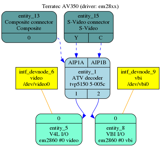
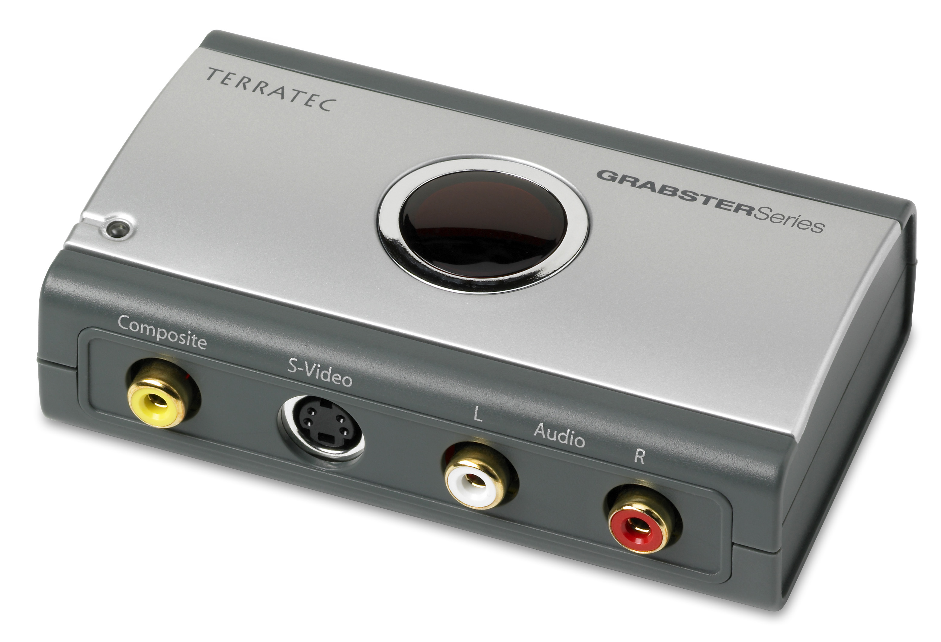